

A hydraulic proportional remote control converts an operator’s joystick or other continuously variable input into a wireless command, then translates that command into a proportional hydraulic control signal. The signal ultimately changes the position of a hydraulic valve spool or the command sent to a valve controller, allowing the machine to control actuator speed, direction or pressure continuously rather than simply switching a function on or off.
The complete process can be understood as:
Joystick movement → transmitter → wireless link → receiver → control signal → valve driver/electronics → proportional hydraulic valve → hydraulic actuator
This architecture is used in equipment such as construction machinery, cranes, concrete pump trucks, forestry equipment, agricultural machinery and other mobile or industrial hydraulic systems. Nomi’s product range is focused on wireless remote-control solutions for hydraulic proportional systems and heavy-duty machinery.
The important point is that the remote control does not create hydraulic power by itself. It provides the control command that determines how the hydraulic system uses the available power.
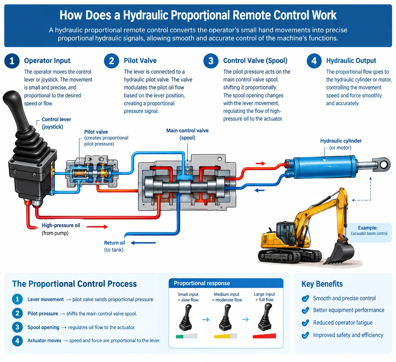
1. What Is a Hydraulic Proportional Remote Control?
A hydraulic proportional remote control is a wireless control system designed to regulate hydraulic functions according to the operator’s input position.
A conventional ON/OFF remote generally has two states:
ON → function operates
OFF → function stops
A proportional remote has a continuously variable command:
small joystick movement → small hydraulic command
larger joystick movement → larger hydraulic command
full joystick movement → maximum configured command
This makes it possible to control the speed or movement of a hydraulic actuator progressively.
For example, imagine a hydraulic boom controlled by a joystick.
With an ON/OFF control, the valve may receive essentially a full command as soon as the operator presses the button. The boom can therefore start quickly.
With proportional control, the operator can move the joystick slightly to initiate slow movement, then increase joystick displacement to increase the hydraulic command.
This is particularly useful when the operator needs:
- smooth starting and stopping
- controlled acceleration
- fine positioning
- variable actuator speed
- coordinated movement
- reduced shock during load handling
Danfoss describes proportional valve electronics as systems that can regulate proportional valves using voltage or current inputs and PWM output, with functions such as ramp control and deadband adjustment.
2. The Basic Architecture
A typical hydraulic proportional wireless control system contains several functional layers.
| Component | Main function |
|---|---|
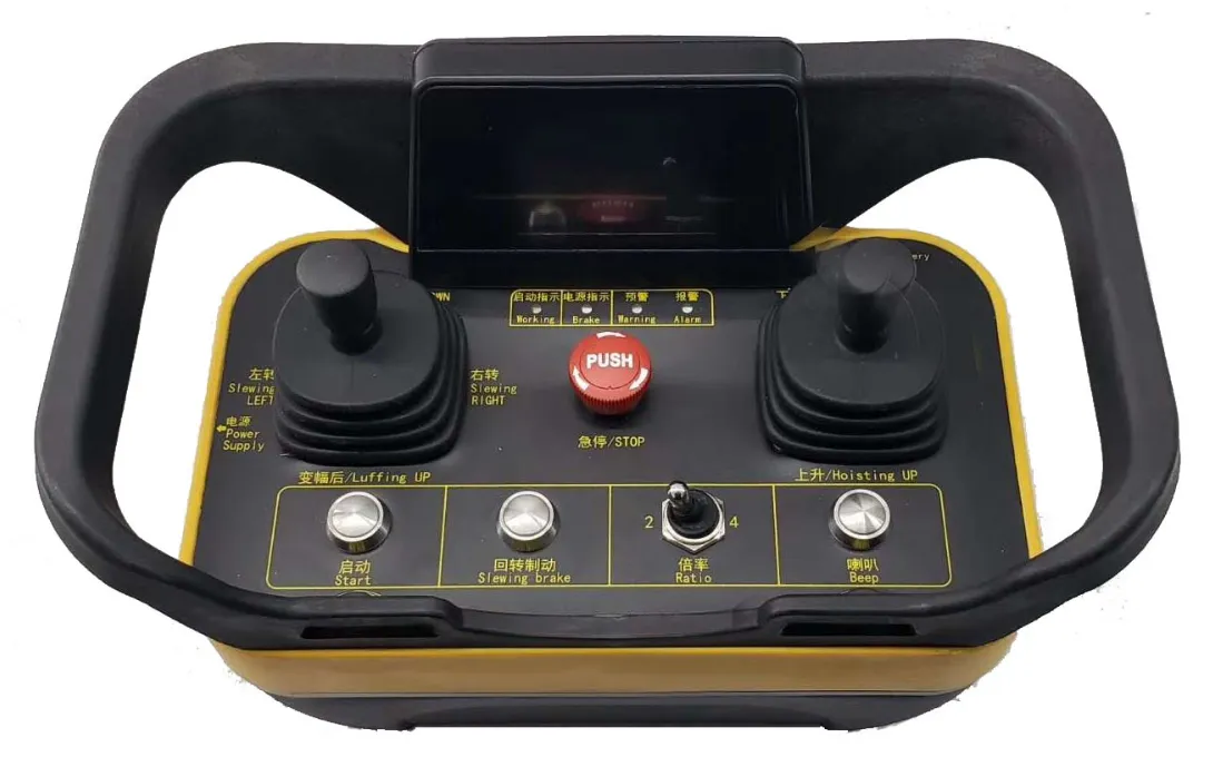
| Joystick or proportional control | Measures the operator’s command |
| Wireless transmitter | Converts the command into a radio transmission |
| Wireless receiver | Receives and decodes the command |
| Controller or valve amplifier | Converts the command into the required valve-driving signal |
| Proportional hydraulic valve | Regulates hydraulic flow, pressure or direction |
| Hydraulic actuator | Produces mechanical movement |
| Feedback system, if used | Provides information about position or system status |
A simplified control path looks like this:
Operator
↓
Proportional joystick
↓
Wireless transmitter
↓
Radio communication
↓
Wireless receiver
↓
Analog / PWM / current / CAN output
↓
Valve electronics
↓
Proportional valve
↓
Hydraulic actuator
Not every machine uses exactly this architecture.
Some valves have separate amplifiers. Some valves have integrated electronics. Some mobile machines use a central ECU and CAN communication instead of directly driving each valve.
Danfoss, for example, offers proportional hydraulic actuators that can accept high-current PWM, voltage, ratio-metric or CAN-based commands depending on the product configuration.
That is why a hydraulic remote control should not be specified only by saying:
“I need a wireless remote with four proportional functions.”
The electrical and hydraulic interfaces also need to be identified.
3. Step 1: The Joystick Creates a Proportional Command
The process begins with the operator.
A proportional joystick is different from a simple push button because the system needs to determine how far the joystick has moved, not merely whether it has been activated.
For example:
- joystick centered = approximately zero command
- joystick moved 20% = low command
- joystick moved 50% = medium command
- joystick moved 100% = maximum command
The actual relationship does not necessarily have to be perfectly linear.
A control system may apply:
- dead zone
- scaling
- gain
- curve adjustment
- ramping
- direction reversal
- maximum output limitation
These settings allow the electronic control system to match the remote’s behavior to the hydraulic machine.
For example, a machine that responds aggressively at low joystick displacement may benefit from a different control curve from a machine requiring fine positioning.
4. Step 2: The Transmitter Converts the Command Into a Wireless Message
The transmitter reads the joystick position and other controls such as:
- push buttons
- toggle switches
- selector switches
- emergency-stop controls
- rotary controls
- other proportional inputs
The control information is then encoded into a wireless communication packet.
The transmitter does not normally send hydraulic oil pressure or hydraulic power.
It sends information representing the operator’s command.
For example, conceptually, a message could contain information such as:
| Parameter | Example meaning |
|---|---|
| Channel 1 | Boom up/down command |
| Channel 2 | Boom extension/retraction |
| Channel 3 | Winch command |
| Channel 4 | Slewing command |
| Switch 1 | Auxiliary function |
| E-stop status | Emergency-stop state |
| Battery status | Transmitter power condition |
The exact data structure depends on the remote-control system.
Wireless systems can use different radio technologies and frequency bands. Tele Radio, for example, lists hydraulic remote-control systems using configurations including 433 MHz, 915 MHz and 2.4 GHz, depending on the system.
The radio frequency itself, however, does not determine whether a system is proportional.
Proportionality comes from the control architecture and signal processing.
5. Step 3: The Receiver Decodes the Wireless Command
The receiver is installed on the machine.
Its job is to:
- receive the wireless message
- verify that the message is valid
- identify the transmitter
- decode joystick and switch information
- apply configured control logic
- generate the required machine-side output
The receiver therefore acts as the bridge between the wireless control system and the machine’s electrical or hydraulic control system.
This is one of the most important components to consider when selecting a hydraulic remote.
A transmitter may look suitable because it has the right number of joysticks, but that does not guarantee compatibility with the machine.
The receiver must also provide the correct output architecture.
6. What Does the Receiver Output?
This is where hydraulic proportional remote controls become more technically interesting.
The receiver may provide different types of outputs depending on the machine architecture.
Common possibilities include:
| Output | Typical role | Main consideration |
|---|---|---|
| 0-10 V | Analog valve/controller command | Must match input specification |
| 4-20 mA | Analog industrial control | Good for noise-resistant signal transmission |
| PWM | Proportional valve control | Frequency and current requirements matter |
| CAN / CANopen / J1939 | Digital machine communication | Protocol and message mapping required |
| Relay output | ON/OFF functions | Not itself proportional |
| Direct current control | Valve coil command | Current range must match valve |
Tele Radio’s hydraulic remote-control systems, for example, support proportional, analog, relay and CAN functionality, while its receivers can provide PWM and CAN-based outputs depending on configuration.
The critical point is:
The receiver output must match the machine’s control interface.
There is no universally correct proportional signal.
7. How Does the Electrical Signal Control the Hydraulic Valve?
A proportional hydraulic valve uses an electrical command to influence valve operation.
A simplified example is:
Higher control current → greater solenoid force → greater spool displacement → greater hydraulic opening → higher flow
The exact relationship depends on the valve design.
Danfoss explains that proportional valves can be controlled using current, and that current-controlled PWM is commonly used because coil resistance changes with temperature. This matters because directly treating voltage as the controlled variable can change current as the coil temperature changes.
This is one reason why engineers need to look beyond the remote-control transmitter.
The remote may provide the command, but the valve and its electronics determine how that command becomes hydraulic movement.
8. What Is PWM in a Hydraulic Proportional Control System?
PWM stands for Pulse Width Modulation.
Instead of supplying a continuously variable DC voltage in a simple way, the controller rapidly switches the electrical output and controls the effective command through the pulse characteristics.
For proportional hydraulic control, PWM may be combined with current regulation.
The exact frequency and electrical parameters must follow the valve or valve-driver manufacturer’s specifications.
Danfoss documentation notes that many proportional valves use current-based control with PWM and provides product-specific recommendations rather than treating one PWM setting as universally applicable.
This is important when specifying a remote control.
A buyer should not simply tell a supplier:
“We need PWM output.”
A better specification includes:
- required PWM frequency
- voltage
- current range
- number of channels
- whether current control is required
- valve model
- valve coil specifications
- whether the valve has integrated electronics
9. What Is the Role of a Valve Amplifier?
A valve amplifier, sometimes called a proportional valve driver, sits between the control command and the valve coil in many systems.
Its job can include:
- converting an input command into controlled valve current
- PWM generation
- current regulation
- deadband compensation
- gain adjustment
- ramp control
- dither compensation
- protection and diagnostics
For example:
Remote receiver → 0-10 V command → valve amplifier → controlled solenoid current → proportional valve
In another system:
Remote receiver → CAN command → machine ECU → valve electronics → proportional valve
And in another architecture:
Remote receiver → PWM/current output → proportional valve
Therefore, there is no single universal wiring diagram for every hydraulic proportional remote.
Danfoss proportional valve electronics include functions such as PWM generation, ramp functions, overload protection and adjustable deadband and gain.
10. Why Deadband Matters
One commonly overlooked parameter is deadband.
A hydraulic proportional valve may not begin moving immediately when a very small electrical command is applied.
There can be a range around the zero position where the input changes but the valve produces little or no useful movement.
If the deadband is not properly configured, the operator may experience:
- joystick movement with little machine response
- inconsistent initial movement
- unwanted creeping
- poor low-speed control
The control system may therefore apply deadband compensation.
However, too much compensation can also be undesirable because it can make the machine respond too aggressively near the joystick center.
The correct setting depends on the actual valve and machine.
This is why a proportional remote should be commissioned as a system, not simply installed as an isolated electronic component.
11. Why Ramping Matters
Ramping controls how quickly the command changes.
Without ramping:
0% → 100% command
could theoretically occur very quickly.
With ramping:
0% → 20% → 40% → 60% → 80% → 100%
over a configured period.
The actual implementation is continuous rather than necessarily using those discrete steps.
Ramping can be useful for:
- smoother acceleration
- smoother deceleration
- reducing mechanical shock
- improving load handling
- reducing abrupt hydraulic movement
Danfoss proportional valve electronics specifically include ramp functions for controlling the rate of increase and decrease of output.
For cranes and load-handling machinery, this can be especially important because abrupt hydraulic movement can affect load stability and positioning.
12. What Is Hysteresis?
Hysteresis describes the difference in valve output depending on whether the control input is increasing or decreasing.
For example, a valve may produce slightly different flow at the same nominal control input depending on whether the operator reached that position while increasing or decreasing the command.
Hydraulic valve hysteresis can result from several factors, including mechanical characteristics, friction and electromagnetic behavior.
Danfoss identifies hysteresis as an important characteristic of proportional valves and provides it as a technical parameter for valve performance.
This matters because a remote control with high-resolution joystick sensing does not automatically guarantee equally high hydraulic positioning accuracy.
The complete system includes:
joystick resolution + wireless communication + receiver processing + valve electronics + valve characteristics + hydraulic circuit + actuator/load
13. What About Dither?
Some proportional hydraulic systems use dither, a small controlled oscillating component applied to the valve command.
The purpose is generally to reduce the effects of static friction and improve valve response.
Dither is a valve-control parameter, not simply a “remote control feature.”
The appropriate frequency and amplitude depend on the valve and control electronics.
Danfoss proportional valve electronics include adjustable dither compensation on certain amplifier systems.
Therefore, if a buyer is replacing an existing remote system, it is worth checking whether the current valve amplifier already has specific dither settings.
Changing the remote without preserving compatible valve-control parameters can change machine behavior.
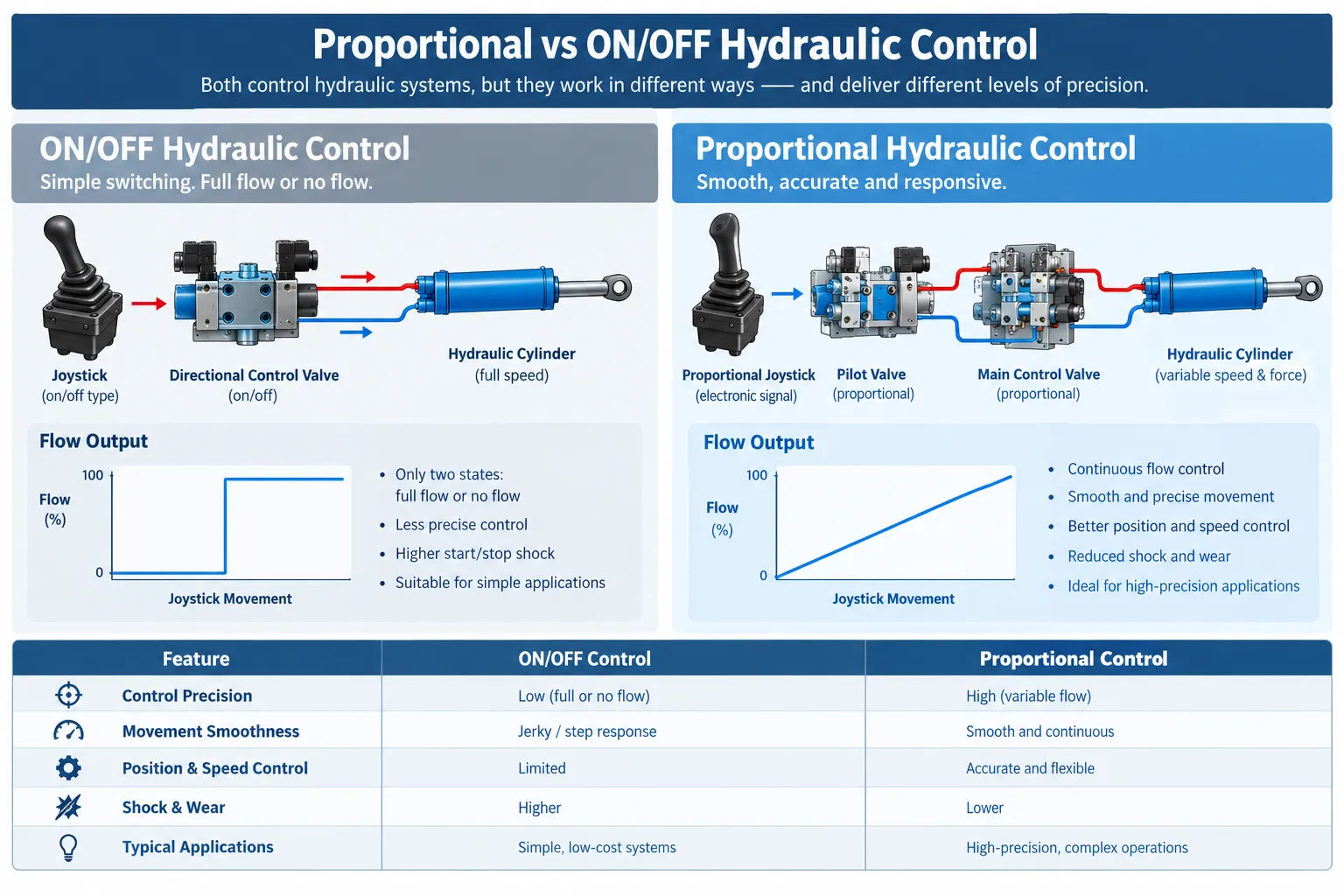
14. Proportional vs ON/OFF Hydraulic Remote Control
The fundamental difference is the number of useful command states.
| Characteristic | ON/OFF Remote | Proportional Remote |
|---|---|---|
| Control type | Binary | Continuously variable |
| Operator input | Button/switch | Joystick/paddle/analog input |
| Valve command | Full ON/OFF | Variable |
| Speed control | Limited | Variable |
| Fine positioning | Limited | Better suited |
| Installation complexity | Usually lower | Usually higher |
| Electronics | Simpler | More complex |
| Cost | Generally lower | Generally higher |
| Best suited for | Simple functions | Variable-speed hydraulic movement |
An ON/OFF system can be entirely appropriate when the machine only needs a simple function such as:
- start/stop
- auxiliary valve activation
- simple hydraulic switching
A proportional system becomes more valuable when the operator needs to control how fast or how precisely the hydraulic function moves.
Nomi’s own product information distinguishes proportional hydraulic control from simpler switching control and describes proportional systems as using continuously variable valve commands for actuator speed control.
15. When Should You Use a Hydraulic Proportional Remote Control?
A proportional system is generally worth considering when the application requires:
Smooth movement
The operator needs gradual acceleration rather than abrupt hydraulic activation.
Variable speed
The same function needs to operate slowly during positioning and faster during normal movement.
Fine positioning
Examples include positioning a crane load or controlling machinery close to another object.
Multiple hydraulic functions
A single joystick system can provide proportional control for several hydraulic functions.
Remote operator positioning
Wireless control can allow the operator to stand in a position with better visibility of the work area, subject to the machine’s safety architecture and applicable requirements.
Retrofit applications
Wireless proportional systems can sometimes be integrated into existing hydraulic machinery, but compatibility must be verified rather than assumed.
16. When Is Proportional Control Not Necessary?
Proportional control is not automatically the best solution for every hydraulic machine.
It may add unnecessary complexity when:
- the hydraulic function only requires ON/OFF operation
- precise speed control provides little operational value
- the existing hydraulic architecture cannot accept proportional control without major modification
- the application has very simple operator requirements
- the additional control electronics are not justified by the machine’s operating needs
The correct question is not:
“Is proportional control better?”
It is:
“Does the machine benefit enough from variable hydraulic control to justify the additional system complexity?”
17. Direct Valve Control vs ECU/CAN Control
Modern mobile machinery can use different control architectures.
Architecture A: Analog or PWM control
A simplified system may look like:
Joystick → transmitter → receiver → analog/PWM output → valve driver → valve
This approach can be relatively straightforward when the hydraulic valve has a known electrical interface.
Architecture B: CAN-based control
A more integrated machine may use:
Joystick → transmitter → receiver → CAN → machine ECU → valve electronics → hydraulic valve
CAN-based systems can reduce the number of individual signal wires and allow digital communication between control devices.
However, CAN integration introduces another layer of engineering.
The system may need to define:
- CAN message ID
- data byte allocation
- scaling
- direction
- resolution
- update rate
- enable logic
- error handling
- machine-specific control logic
Therefore, a buyer specifying a CAN hydraulic remote should provide the machine’s CAN communication requirements rather than simply requesting “CAN output.”
18. What Makes a Hydraulic Proportional Remote Control System Perform Well?
The remote control itself is only one part of the system.
Performance depends on the complete chain.
| Factor | Why it matters |
|---|---|
| Joystick sensing | Determines command resolution |
| Wireless communication | Determines reliable command transmission |
| Receiver processing | Determines how commands are interpreted |
| Output interface | Must match machine electronics |
| Valve driver | Determines current and control behavior |
| Valve characteristics | Affect response, hysteresis and flow |
| Hydraulic circuit | Determines actual actuator behavior |
| Load | Changes machine response |
| Calibration | Matches command to actual machine behavior |
| Safety logic | Determines system behavior during faults |
This is an important distinction.
A high-resolution joystick cannot compensate for an incorrectly configured valve.
Likewise, a high-quality hydraulic valve cannot compensate for an incompatible control signal.
19. Common Buyer Mistakes
Mistake 1: Specifying only the joystick layout
For example:
“We need two joysticks and six buttons.”
That describes the operator interface but does not describe the machine interface.
The supplier also needs to know what happens electrically after the receiver.
Mistake 2: Assuming all proportional valves use the same signal
They do not.
Depending on the valve and system architecture, the command may involve:
- current
- PWM
- voltage
- CAN
- integrated electronics
Danfoss documentation demonstrates that different proportional valve systems can use different control methods.
Mistake 3: Giving only the machine model
A machine model is useful, but it may not be sufficient.
Different machine configurations can use different valve blocks, controllers or electrical systems.
If possible, provide:
- machine model
- machine year
- hydraulic valve manufacturer
- valve model
- valve photos
- existing controller information
- system voltage
- wiring information
Mistake 4: Ignoring the valve coil specification
The valve coil’s electrical requirements are critical.
The remote receiver or valve driver must be capable of providing the required electrical output.
Mistake 5: Treating “proportional” as a guarantee of precision
A proportional signal allows variable control.
It does not automatically mean the machine will have a particular level of positioning accuracy.
Actual performance depends on the valve, hydraulics, load, control tuning and mechanical system.
Mistake 6: Forgetting fail-safe behavior
Industrial wireless hydraulic control systems need to consider what happens if:
- the transmitter loses power
- the receiver loses the radio link
- the battery becomes depleted
- communication is interrupted
- an emergency stop is activated
- a wiring fault occurs
These functions should be evaluated according to the machine’s safety design and applicable requirements.
Tele Radio, for example, describes fail-safe behavior for conditions such as loss of range, dead battery or transmitter failure in its hydraulic remote-control systems.
The exact safety architecture must be engineered for the specific machine and application.
20. What Information Should You Give a Supplier?
If you are requesting a quotation for a hydraulic proportional remote control, the following information can significantly reduce back-and-forth communication.
Machine information
- Machine type
- Machine model
- Machine manufacturer
- Machine year, if relevant
Hydraulic information
- Hydraulic valve manufacturer
- Valve model
- Number of valve sections/spools
- Proportional or ON/OFF valve
- Hydraulic functions to be controlled
- Existing hydraulic schematic, if available
Electrical information
- 12 VDC or 24 VDC system
- Valve coil voltage
- Valve coil current range
- Existing amplifier/controller
- Existing PLC or ECU
- Required output type
Communication information
If CAN is required:
- CAN protocol
- J1939, CANopen or proprietary CAN
- CAN message information
- Required communication parameters
Remote-control requirements
- Number of joysticks
- Number of proportional channels
- Number of ON/OFF functions
- Emergency stop requirement
- Display requirement
- Operator feedback requirements
- Required operating range
- Environmental requirements
Existing equipment
The most useful documents can include:
- photos of the existing remote
- photos of the receiver
- photos of the hydraulic valve
- receiver nameplate
- valve nameplate
- wiring diagram
- electrical schematic
- hydraulic schematic
For OEM or retrofit projects, these details are generally more valuable than simply providing the machine’s product name.
21. How to Evaluate a Supplier’s Quotation
When comparing hydraulic proportional remote-control suppliers, do not compare only the number of joysticks or the wireless range.
A better comparison includes the complete system interface.
| Evaluation item | Question to ask |
|---|---|
| Transmitter | Does the layout match the machine functions? |
| Receiver | Does it support the required outputs? |
| Proportional channels | How many are available? |
| Output type | PWM, current, voltage or CAN? |
| Valve compatibility | Which valve models are supported? |
| Power supply | Is 12 VDC or 24 VDC required? |
| Calibration | Can deadband, gain and ramp be adjusted? |
| Safety | What happens after signal loss? |
| Diagnostics | Are faults visible to the operator or technician? |
| Environmental protection | Is the enclosure suitable for the application? |
| Integration | Is wiring or programming support available? |
| Customization | Can channel mapping be modified? |
| Documentation | Are wiring diagrams and configuration information provided? |
A quotation that looks cheaper may require additional valve electronics, wiring changes or engineering work.
The real comparison should therefore consider total integration cost, not only the transmitter price.
22. A Practical Example: Wireless Crane Control
Consider a hydraulic crane with four proportional functions:
- boom movement
- telescoping
- winch
- slewing
The operator moves the joystick for the boom.
Stage 1
The joystick position is detected.
Stage 2
The transmitter converts the position into a wireless command.
Stage 3
The receiver receives and decodes the command.
Stage 4
The receiver produces the required output, such as PWM, analog, current or CAN.
Stage 5
The valve electronics interpret that command.
Stage 6
The proportional hydraulic valve changes its spool position.
Stage 7
Hydraulic flow to the actuator changes.
Stage 8
The boom moves at the resulting hydraulic speed.
The operator can then move the joystick further to request a larger command.
The entire process happens continuously while the control system remains active.
This is the fundamental principle behind wireless proportional hydraulic control.
23. The Most Important Concept to Remember
A hydraulic proportional remote control is not simply a wireless joystick.
It is an interface between:
human input
and
electro-hydraulic control
The quality of the final result depends on whether all parts of the chain are compatible.
A useful engineering model is:
Operator input → wireless communication → command processing → electrical valve control → hydraulic flow → actuator movement
Each stage has its own specifications.
For example:
- joystick resolution affects input sensitivity
- wireless architecture affects communication reliability
- receiver configuration affects command mapping
- valve-driver design affects current control
- valve characteristics affect hydraulic response
- hydraulic circuit design affects actuator behavior
- load conditions affect actual machine movement
Understanding this chain makes it much easier to specify or troubleshoot a hydraulic proportional remote control.
24. FAQ
1. What is a hydraulic proportional remote control?
It is a wireless control system that converts variable operator input, typically from a joystick or proportional paddle, into a command used to control hydraulic valves. Unlike an ON/OFF remote, it can provide variable control over hydraulic functions.
2. How does a proportional hydraulic remote control work?
The joystick position is detected by the transmitter, converted into a wireless command, received by the machine-side receiver and then converted into an appropriate control output. That output controls a proportional hydraulic valve or valve controller, which regulates hydraulic flow or pressure.
3. Does the wireless receiver directly control the hydraulic valve?
Not always. Some systems can provide direct proportional electrical outputs, while others use a separate valve amplifier, machine ECU or integrated valve electronics. The correct architecture depends on the valve and machine.
4. What signals can be used for proportional hydraulic control?
Common interfaces include PWM, current-based signals such as 4-20 mA, voltage signals such as 0-10 V, and digital communication such as CAN. The correct choice depends on the valve and machine controller.
5. What is the difference between proportional and ON/OFF hydraulic remote control?
An ON/OFF remote generally provides discrete states, while a proportional remote provides a continuously variable command. Proportional control is useful when operators need variable speed, smoother movement or more precise positioning.
6. Is CAN better than PWM for hydraulic remote control?
Neither is universally better. CAN can be useful when the machine already uses a digital ECU architecture, while PWM or analog control may be simpler for other hydraulic systems. Compatibility with the existing machine architecture is more important than choosing one signal because it appears more advanced.
7. Why are deadband and ramping important?
Deadband helps define the region around zero command where unwanted movement should be avoided or compensated. Ramping controls how quickly the command increases or decreases. Both can affect how smoothly the hydraulic machine responds.
8. Can a hydraulic proportional remote be added to an existing machine?
Potentially, but compatibility must be evaluated. The hydraulic valve, electrical system, control interface, power supply and safety architecture all need to be considered. Retrofit does not necessarily mean that the original hydraulic valve must be replaced.
9. What information should I provide when asking for a hydraulic remote-control quotation?
Provide the machine model, system voltage, valve manufacturer and model, number of hydraulic functions, required proportional channels, existing controller or ECU information, valve coil specifications and any available wiring or hydraulic diagrams. Photos of the existing valve and receiver can also be useful.
10. Does proportional control automatically mean higher positioning accuracy?
No. Proportional control provides variable command resolution, but actual positioning performance depends on the complete hydraulic and mechanical system, including the valve, actuator, load, control tuning and hydraulic circuit.
