

Industrial radio remote control systems allow an operator to control machinery from a distance by sending commands through a wireless radio link to a receiver mounted on the machine. A complete system is more than a handheld transmitter and a receiver. It normally includes the operator controls, RF communication hardware, command decoding, safety monitoring, machine-side output interfaces, and the electrical, hydraulic, or electronic components that finally create movement.
For a hydraulic machine, the practical control path may look like this:
Operator → joystick or buttons → wireless transmitter → RF communication → receiver → output interface or machine controller → hydraulic valve → actuator
For an electrically driven machine, the final stages may instead be:
Operator → transmitter → RF link → receiver → PLC or drive interface → contactor/VFD/servo drive → motor
This distinction matters when selecting a system. The correct radio remote control is determined not only by the number of buttons or the advertised operating distance, but also by the machine’s control architecture, required safety functions, electrical interfaces, operating environment, and applicable regulations.
What Is an Industrial Radio Remote Control System?
An industrial radio remote control system is a wireless operator-control system used to send commands to machinery without requiring the operator to remain at the machine’s local control station.
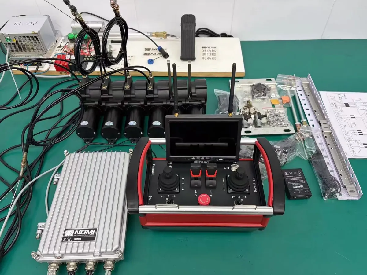
ISO 10968 defines remote operator control as machine control using wired or wireless transmission of signals from a remote control box to a receiving unit located on the machine. The same standard also defines proportional control as control that produces a continuously variable or modulated machine response.
In practical terms, an industrial radio remote control normally has two primary electronic endpoints:
| Component | Primary role |
|---|---|
| Transmitter | Captures operator commands and sends encoded wireless data |
| Receiver | Receives, validates, decodes, and converts wireless commands into machine-side outputs |
However, those two boxes are only the visible part of the system.
Depending on the machine, additional elements may include:
- joystick or push-button input devices.
- emergency-stop and enabling controls.
- microcontroller and command encoder
- RF transceiver and antenna.
- battery and power-management circuitry.
- pairing or machine-identification logic.
- receiver-side watchdog and safety monitoring.
- relay outputs.
- analog or PWM outputs.
- CAN or other machine-network interfaces.
- proportional valve drivers.
- solenoid coils.
- PLC or machine ECU.
- hydraulic valves.
- motors, cylinders, brakes, contactors, or other actuators.
The engineering objective is to move information reliably from the operator’s hand to the machine’s final control element while ensuring that defined fault conditions do not create an unsafe command.
The Six Functional Layers of an Industrial Radio Remote Control System
A useful way to understand an industrial wireless control system is to divide it into six layers.
1. Operator input
The operator begins the control process by moving a joystick, pressing a button, turning a selector, or operating another control element.
2. Wireless transmitter
The transmitter measures the input, processes it, and converts the command into a structured wireless message.
3. RF communication link
The message travels between the transmitter and receiver using a defined radio frequency and communication protocol.
4. Wireless receiver
The receiver accepts valid messages from the paired transmitter, processes the commands, monitors communication status, and produces machine-side outputs.
5. Machine interface
The receiver may connect directly to relays, proportional valve drivers, analog inputs, PWM outputs, CAN interfaces, or a PLC or ECU.
6. Final actuator
The machine’s control element creates the physical response, such as moving a hydraulic spool, energizing a contactor, changing motor speed, or moving a cylinder.
This layered approach is important because a system can be strong at one layer and incompatible at another.
For example, a remote can have an excellent radio link but still be unsuitable for a hydraulic machine if its output interface cannot drive the existing valve system.
1. Transmitter: The Operator’s Control Interface
The transmitter is the component held by the operator. It determines how human movement becomes a machine command.
Common industrial transmitters use:
- push buttons
- single-axis or multi-axis joysticks
- levers
- rotary selectors
- toggle switches
- start controls
- emergency-stop devices
- enabling or dead-man controls
- status LEDs
- displays or diagnostic indicators.
The physical arrangement matters because industrial operators may use gloves, work in rain or dust, or operate the machine while watching the load or working area rather than the remote itself.
A control element should therefore not be selected only by the number of channels it provides. Its mechanical behavior and ergonomics must also match the application.
A push button generally provides a discrete command:
Pressed → ON
Released → OFF
A joystick can provide a continuously variable command:
Neutral → low movement → medium movement → maximum movement.
This is why a joystick is often used when the operator needs fine motion control.
Nomi’s portfolio currently includes both joystick remote controls and push-button remote controls, reflecting the fact that industrial machines may require different control interfaces.
The transmitter usually contains more than switches
Internally, an industrial transmitter may contain:
Input section → processor → safety logic → RF module → antenna
The processor identifies which controls are active and may apply functions such as scaling, deadband, ramping, command validation, or programmed limits.
The RF module then formats and transmits the data.
Battery management is another important function. A low battery condition must be considered as part of system behavior, rather than simply treated as an inconvenience.
A robust design should define what happens when the transmitter loses power during operation.
2. RF Communication Link: More Than “Wireless Range”
The radio link connects the transmitter and receiver.
This is where many product descriptions become overly focused on one number:
“Control distance: 300 m.”
Range is useful, but it is not a complete measure of wireless performance.
Actual communication performance can depend on:
- frequency band.
- transmitter output characteristics.
- receiver sensitivity.
- antenna design
- antenna location
- obstacles
- metal structures.
- machine geometry.
- electromagnetic interference.
- other wireless systems.
- radio protocol.
- communication timing.
- local regulatory limits.
A system that performs well in an open test area may behave differently inside a steel-processing plant, shipyard, tunnel, warehouse, or construction site.
Frequency is not a universal “better or worse” choice
Industrial wireless systems can be designed for different frequency bands depending on the product architecture and target market. Nomi’s current public product pages, for example, show different frequency options across product configurations.
The correct frequency is therefore a product and regulatory question, not simply a matter of choosing the highest number.
For European radio equipment within the applicable scope, ETSI EN 300 220-2 covers short-range devices operating in the 25 MHz to 1,000 MHz range, with a current harmonized version listed by ETSI as version 3.3.1 and cited in the EU Official Journal in 2025.
In the United States, applicable radio-frequency equipment must meet FCC equipment-authorization requirements before it is marketed or imported, subject to the specific regulatory category and available exemptions.
This leads to a practical purchasing rule:
Do not specify the radio frequency before confirming the target market and regulatory requirements.
3. Communication Protocol, Pairing, and Command Validation
A professional industrial remote control must do more than receive a radio signal.
The receiver needs a way to determine whether an incoming transmission is valid and whether it belongs to the correct transmitter-machine pair.
Depending on system architecture, this can involve:
- unique identification.
- pairing
- channel selection
- message validation
- error detection
- sequence monitoring.
- communication watchdogs.
- bidirectional status exchange.
The purpose is to reduce the possibility that another nearby transmitter accidentally controls the machine.
This becomes particularly important in facilities where multiple radio-controlled cranes, vehicles, hoists, or machines operate within the same area.
A practical system architecture should answer four questions:
- Which transmitter is authorized to control this receiver?
- How does the receiver detect an invalid or corrupted message?
- How quickly does the receiver detect a communication failure?
- What happens to machine outputs after communication is lost?
The last question is a safety issue rather than just a communication issue.
4. Receiver: The Machine-Side Interface
The receiver is installed on or inside the machine and provides the bridge between wireless commands and the machine’s control architecture.
A typical receiver can include:
Antenna → RF front end → decoder/processor → command and safety logic → output interface
The actual design varies by manufacturer and application.
A receiver may provide:
| Output type | Typical application |
|---|---|
| Relay output | Contactors, solenoids, on/off functions |
| Digital output | Logic-level or discrete machine inputs |
| Analog voltage | Proportional control interfaces |
| Current output | Current-controlled proportional valves |
| PWM output | Proportional solenoid control |
| CAN interface | Electronic machine controllers and ECUs |
| Fieldbus interface | PLC or industrial control integration |
This is one of the most important parts of system selection.
Channel count is not enough
Suppose a machine has eight functions.
A buyer might assume that an “8-channel remote” will be suitable.
That assumption is incomplete.
The eight functions might require:
- eight relay outputs
- six relay outputs plus two proportional axes.
- four joysticks
- four analog outputs
- CAN messages
- a combination of proportional and discrete commands.
The receiver must therefore be matched to the actual machine interface.
5. Hydraulic Valve Interface: The Critical Layer for Hydraulic Machinery
For hydraulic equipment, the receiver normally does not move the hydraulic actuator directly.
Instead, the electrical command eventually controls a hydraulic valve.
A simplified architecture is:
Wireless transmitter → receiver → valve driver → solenoid/proportional actuator → directional valve → hydraulic actuator
Nomi’s published hydraulic-control architecture similarly describes the sequence from joystick input through wireless communication, receiver output, valve electronics, proportional valve, and hydraulic actuator.
This explains why hydraulic wireless remote control is fundamentally an electro-hydraulic integration problem, not simply a radio-control problem.
On/off hydraulic control
For a conventional directional valve, the receiver may energize a solenoid:
Output ON → solenoid energized → valve spool shifts
This is suitable when the machine function is essentially discrete.
Proportional hydraulic control
For proportional operation, the system must control the valve according to command magnitude.
Conceptually:
Joystick 20% → small valve command
Joystick 50% → medium valve command
Joystick 100% → maximum configured valve command
The actual response may use scaling, deadband, ramping, gain, or a non-linear control curve.
This is why two systems with the same number of joysticks can produce very different machine behavior.
What should be checked?
For a hydraulic retrofit, verify at least:
| Parameter | Why it matters |
|---|---|
| Valve manufacturer and model | Confirms mechanical and electrical compatibility |
| Valve type | Determines on/off or proportional control architecture |
| Coil voltage | Must match the machine-side output |
| Coil current or resistance | Prevents under-driving or overheating |
| Connector type | Determines wiring compatibility |
| Output type | Relay, PWM, analog, current, CAN, etc. |
| Valve driver requirement | Some proportional valves need dedicated electronics |
| Neutral behavior | Determines what happens when command is released |
| Spool characteristics | Affects movement response |
| Existing hydraulic circuit | Determines whether the retrofit architecture is practical |
Nomi’s current hydraulic retrofit material specifically emphasizes identifying the valve manufacturer, model, coil specifications, electrical system voltage, and whether the valve is on/off or proportional before selecting the retrofit interface.
For buyers, this produces an important rule:
Send the valve and control-system information to the supplier, not just the machine name and number of channels.
6. Machine Controller, PLC, ECU, and Drive Integration
Not every industrial remote control connects directly to an actuator.
Modern machinery may already contain a PLC, vehicle ECU, machine controller, or distributed electronic control architecture.
In this case, the remote system can function as a wireless operator interface.
The architecture may be:
Transmitter → RF link → Receiver → PLC/ECU → machine logic → actuator
This arrangement has an important advantage: existing machine logic remains responsible for interlocks, sequencing, limits, and other functions.
A recent industrial integration reference describes this model as a remote system in which the receiver provides discrete or networked commands while the PLC or PAC performs machine logic and safety-related control functions.
This leads to a key design distinction:
Command layer
“What does the operator want the machine to do?”
Machine-control layer
“Is that command allowed, and how should the machine execute it?”
Safety layer
“What must happen if the operator, wireless link, controller, or another component fails?”
A wireless remote control system should not automatically be treated as the entire control architecture simply because it provides an emergency-stop button.
7. Emergency Stop and Fail-Safe Operation
Wireless control creates a specific engineering problem:
What happens when the communication link stops working?
Possible causes include:
- transmitter out of range.
- radio interference.
- transmitter battery failure.
- receiver power loss.
- damaged antenna.
- internal transmitter fault.
- receiver fault.
- communication protocol failure.
A properly designed system needs a defined response.
The response is application-specific, but the principle is that an identified fault should not leave the machine continuing to execute an uncontrolled command.
ISO 13850:2015 provides functional requirements and design principles for emergency-stop functions on machinery.
Official ISO page for ISO 13850:2015
IEC 60204-1:2016+A1:2021 addresses the electrical equipment of machinery and includes requirements covering areas such as emergency stop, control-circuit protection, and safe torque-off-related aspects.
Official IEC page for IEC 60204-1:2016+A1:2021
The emergency stop is part of the machine safety system
This distinction is important.
An emergency-stop button on a transmitter is an input device.
The complete emergency-stop function includes the logic, switching elements, machine interface, and final energy-control mechanism necessary to bring the machine to the defined safe condition.
For this reason, simply stating:
“The remote control has an emergency-stop button.”
does not fully describe the safety architecture.
8. Safety-Related Control Systems and Performance Levels
ISO 13849-1:2023 provides a methodology and requirements for designing and integrating safety-related parts of control systems that perform safety functions. It applies across electrical, hydraulic, pneumatic, and mechanical technologies.
Official ISO page for ISO 13849-1:2023
The key point for a remote-control buyer is that the required safety performance must be derived from the machine’s risk assessment.
ISO 12100:2010 establishes principles and a methodology for machinery risk assessment and risk reduction. ISO confirms that this edition remains current following its 2022 review, although a replacement standard is under development.
Official ISO page for ISO 12100:2010
This means a buyer should not begin with:
“I want PL d.”
The better process is:
Identify hazards → perform risk assessment → determine required safety functions → determine required performance → design and validate the control system
The required Performance Level or SIL is therefore not something that should be selected simply because a supplier advertises it.
9. Preventing Unexpected Machine Start-Up
Industrial wireless systems also need to address startup behavior.
Consider this sequence:
- The machine has lost radio communication.
- Communication is restored.
- The transmitter still has a joystick displaced from neutral.
- The machine immediately starts moving.
That behavior may be unacceptable depending on the machine and risk assessment.
ISO 14118:2017 addresses prevention of unexpected machine start-up, including energy sources such as electrical, hydraulic, pneumatic, stored energy, and external influences.
Official ISO page for ISO 14118:2017
A practical remote-control architecture may therefore include a deliberate startup sequence, such as:
Power on → transmitter/receiver validation → emergency stop reset → start command → motion command
The exact sequence must be determined by the machine design and applicable safety requirements.
10. Proportional Remote Control vs Push-Button Remote Control
The most appropriate control style depends on the machine’s required response.
| Requirement | Push-button system | Joystick/proportional system |
|---|---|---|
| Simple ON/OFF functions | Suitable | Suitable |
| Fixed-speed motion | Suitable | Suitable |
| Fine positioning | Limited | More suitable |
| Variable speed | Limited | Suitable |
| Smooth hydraulic movement | Usually limited | More suitable |
| Simple hoist functions | Common | Also possible |
| Multi-axis proportional operation | Not ideal | Suitable |
| Complex hydraulic machinery | Depends on machine | Often more appropriate |
A push-button remote can be technically excellent for a crane with well-defined discrete movements.
A proportional joystick system becomes more relevant when the operator needs to continuously regulate movement.
The important point is that “proportional” describes the machine command behavior, not merely the physical shape of the transmitter.
A joystick connected to a system that only produces relay ON/OFF outputs is not automatically a proportional hydraulic-control solution.
11. Receiver Outputs: Relay, Analog, PWM, and CAN
The output interface is often one of the most misunderstood specifications.
Relay output
Relay outputs are useful for switching discrete functions such as:
- contactors
- directional solenoids
- auxiliary functions
- lights
- horns
- start/stop circuits.
Analog output
Analog output can represent command magnitude using a continuous signal such as voltage or current, depending on the system design.
This can be appropriate for proportional valve electronics, drives, or other analog-controlled equipment.
PWM output
PWM can be used to control proportional solenoids by varying the effective control command.
The actual valve response depends on the valve driver, solenoid characteristics, current regulation, dither settings, and hydraulic system.
CAN interface
CAN is commonly used where the machine already has an electronic control network.
In such systems, the receiver may transmit command information to an ECU instead of directly energizing a valve coil.
For procurement, the correct question is therefore not:
“How many outputs does the receiver have?”
A better question is:
“What type of output does each required machine function need?”
12. Antenna and Receiver Installation
An antenna is a small component with a large effect on real-world wireless performance.
A theoretically good radio system can perform poorly if the antenna is:
- shielded by metal.
- mounted too close to high-noise electronics.
- installed at an unsuitable orientation.
- placed in a poor location.
- connected with an inappropriate cable or connector.
Industrial machinery creates additional challenges because many machines contain large metal structures.
For a crane, the receiver may be mounted high above the operating area.
For an excavator or mobile machine, the receiver may be mounted within a compact engine or electrical compartment.
For a concrete pump truck, the receiver location can also affect exposure to vibration, water, dirt, and electromagnetic noise.
Therefore, antenna selection and placement should be considered part of system installation rather than treated as an afterthought.
13. Environmental Protection: IP Rating Is Only One Specification
Industrial remotes can operate outdoors, in factories, on construction sites, around hydraulic oil, in dusty environments, or under frequent vibration.
The enclosure therefore needs an appropriate environmental design.
Relevant characteristics may include:
- ingress protection
- operating temperature
- impact resistance
- vibration resistance
- chemical resistance
- UV exposure
- connector sealing
- cable protection.
- battery enclosure design.
IP ratings are useful, but they do not tell the entire durability story.
For example, two products may have the same IP rating but different resistance to vibration, impact, temperature cycling, or mechanical wear.
A better procurement process considers the complete operating environment.
14. Industrial Radio Remote Control Systems for Hydraulic Machinery
Hydraulic machinery is a particularly important application because the remote control may need to reproduce the behavior of manual hydraulic controls.
Nomi’s current public portfolio focuses on industrial wireless remote-control solutions for hydraulic proportional systems, cranes, excavators, tower cranes, winches, and other heavy-duty equipment.
For hydraulic retrofits, the overall architecture may be:
Existing hydraulic circuit
↓
Valve and solenoid interface
↓
Receiver/output electronics
↓
Wireless transmitter
The retrofit does not necessarily mean replacing the entire hydraulic power system.
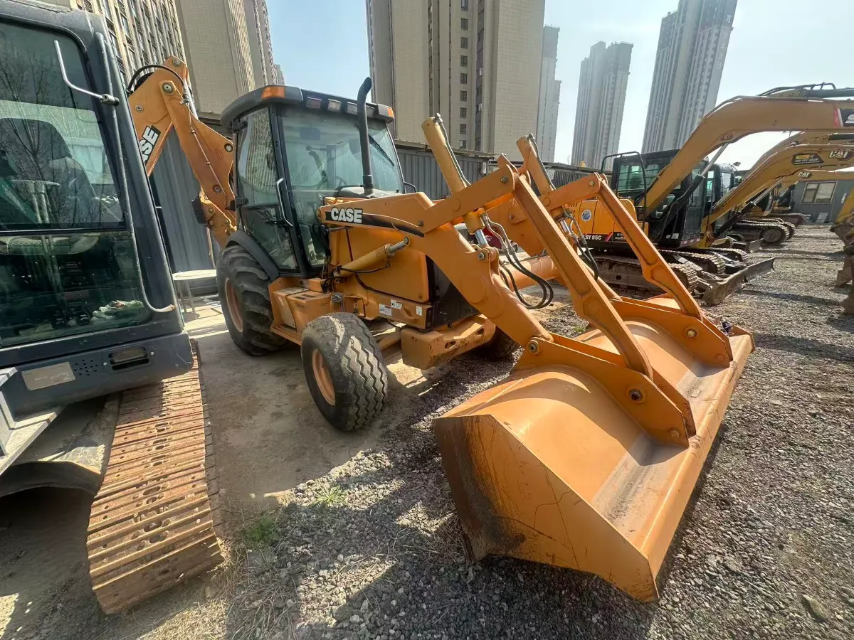
Nomi’s published retrofit material describes an approach in which the existing hydraulic circuit can be retained while electrically actuated valve interfaces and a receiver are added to provide wireless control.
This is useful for machines that already have functional hydraulic pumps, valves, cylinders, motors, and hydraulic circuits but need remote operator control.
15. Application Examples
Industrial radio remote control systems are used across many machine categories, but the required architecture changes with the application.
Cranes and hoists
Typical commands include:
- hoist up/down
- trolley travel
- bridge travel
- auxiliary functions
- start/stop
- emergency stop
The system may use push buttons, two-step controls, joysticks, or combinations.
Nomi currently provides construction crane remote controls as part of its industrial remote-control portfolio.
Excavators
An excavator can require simultaneous multi-axis operation, making proportional control more relevant.
Potential functions include:
- boom
- arm
- bucket
- swing
- travel
- auxiliary attachments
For retrofit projects, industrial hydraulic excavator remote-control kits require particularly careful examination of the original hydraulic and electrical interfaces.
Concrete pump trucks
Control requirements can include:
- boom movement
- pump functions
- auxiliary hydraulics
- engine-related functions
- emergency stop.
Because boom positioning and hydraulic control often require smooth motion, proportional operator control can be important.
Winches and specialized machinery
Winch control may require:
- direction
- variable speed
- brake behavior
- auxiliary functions
- safe stopping
Here, the relationship between the remote command and the final drive or hydraulic motor is critical.
16. What Should Buyers Specify Before Requesting a Quote?
A request such as:
“Please quote an industrial wireless remote control for my excavator.”
is usually not enough for an accurate engineering quotation.
A better RFQ contains the following information.
| Specification | Example of information to provide |
|---|---|
| Machine type | Excavator, crane, pump truck, loader, winch |
| Machine model | Manufacturer and exact model |
| Control method | Hydraulic, electrical, electronic, PLC |
| Number of functions | 4, 6, 8, 12, etc. |
| Control type | On/off, proportional, mixed |
| Joystick axes | Number and axis configuration |
| Existing valve | Manufacturer and model |
| Solenoid voltage | 12 VDC, 24 VDC, etc. |
| Solenoid current | Rated current or resistance |
| Connector | Existing connector type |
| Machine voltage | 12 V, 24 V, other |
| Required output | Relay, analog, PWM, CAN |
| Emergency stop | Existing safety circuit and required behavior |
| Operating environment | Indoor, outdoor, wet, dusty, marine, etc. |
| Temperature | Minimum and maximum ambient temperature |
| Required working distance | Approximate real operating area |
| Country | Determines radio and regulatory requirements |
| Required documents | Declaration, test reports, wiring diagrams, manuals |
| Existing wiring diagram | Strongly recommended |
| Existing hydraulic schematic | Strongly recommended |
This type of information allows a supplier to evaluate the actual system rather than selecting a generic remote based solely on channel count.
17. Common Purchasing Mistakes
Mistake 1: Choosing by control distance alone
A long advertised range does not compensate for an incompatible machine interface.
For a retrofit, compatibility should be confirmed before range becomes the primary comparison factor.
Mistake 2: Choosing by channel count
“8 channels” does not describe whether those channels are relay, proportional, analog, PWM, or CAN commands.
Mistake 3: Assuming every joystick system is proportional
The joystick mechanism and the electrical output architecture are separate specifications.
Mistake 4: Treating IP67 as proof of complete industrial durability
Ingress protection is valuable, but vibration, impact, temperature, connector quality, and mechanical durability also matter.
Mistake 5: Assuming CE or FCC automatically means machine-safety compliance
Radio authorization and machinery safety are different regulatory questions.
A radio device can satisfy applicable RF requirements without automatically satisfying the complete machine safety architecture.
Mistake 6: Ignoring what happens after signal loss
The buyer should explicitly ask:
What happens to each output when communication is interrupted?
Mistake 7: Ignoring startup behavior
The system should have a defined behavior following power restoration, transmitter replacement, pairing, or communication recovery.
Mistake 8: Failing to provide the original valve information
For hydraulic equipment, the valve manufacturer, valve model, coil voltage, current, connector, and control type can be more important than the machine brand name.
18. Standards and Compliance: What Should Be Verified?
The following standards are especially relevant depending on the machine and market.
| Standard / framework | Main subject | Why it matters |
|---|---|---|
| ISO 12100:2010 | Machinery risk assessment and risk reduction | Establishes the overall safety-analysis framework |
| ISO 13849-1:2023 | Safety-related parts of control systems | Relevant when remote-control functions contribute to safety functions |
| ISO 13850:2015 | Emergency-stop function | Relevant to emergency-stop design |
| ISO 14118:2017 | Prevention of unexpected start-up | Relevant to startup and restart behavior |
| IEC 60204-1:2016+A1:2021 | Electrical equipment of machines | Relevant to machine electrical control and emergency-stop implementation |
| ISO 15817:2012 | Remote operator control systems for earth-moving machinery | Particularly relevant to remotely operated earth-moving machines |
| ETSI EN 300 220-2 | Applicable short-range radio equipment | Relevant to certain EU radio-spectrum compliance cases |
| FCC equipment authorization rules | RF equipment in the United States | Relevant to applicable US radio equipment |
The scope of ISO 15817 is worth emphasizing. ISO states that it applies to remote operator control systems used on earth-moving machinery as defined in ISO 6165. It does not establish a universal framework for every industrial wireless remote-control application.
For this reason, buyers should identify the specific machine standard, regional radio requirements, and safety requirements that apply to their installation.
19. A Practical Selection Sequence
A good selection process can be simplified into seven steps.
Step 1: Define the machine
Identify the exact machine type, model, control system, and operating environment.
Step 2: List every required function
Separate functions into:
ON/OFF
proportional
auxiliary
safety-related
Step 3: Identify the existing machine interface
Determine whether the machine expects:
relay → analog → PWM → CAN → PLC input → ECU command
Step 4: Identify the actuator interface
For hydraulic machines, document the valve model, solenoid specifications, and required driver characteristics.
Step 5: Define the safety architecture
Determine:
- emergency-stop behavior
- signal-loss behavior
- unexpected-start prevention
- reset behavior
- local/manual control relationship
Step 6: Verify environmental and radio requirements
Check:
- temperature
- IP rating
- impact/vibration
- operating area
- radio band
- regional approval
- EMC requirements
Step 7: Ask for engineering documents before purchase
A serious RFQ should ideally be supported by:
- wiring diagram
- terminal assignment
- output specification
- machine interface description
- installation instructions
- safety documentation
- radio compliance documentation
- applicable test reports or declarations
20. The Most Important Specification Is Often Not the Radio Range
When comparing industrial radio remote control systems, buyers naturally focus on visible specifications:
range
channel count
IP rating
battery life
These matter, but for many machine-integration projects there is another question that comes first:
Can the system correctly interface with the machine’s existing control architecture?
For hydraulic machinery, that means checking the valve and solenoid interface.
For PLC-controlled machinery, it means checking the communication method and machine-side logic.
For cranes and hoists, it means understanding the existing control circuit and safety functions.
For hazardous environments, it also means verifying the specific hazardous-area certification requirements rather than assuming a standard industrial enclosure is sufficient.
This is one of the most useful ways to compare remote-control suppliers.

21. How Nomi Fits Into This System Architecture
Nomi’s current public website positions the company around industrial wireless remote control solutions for hydraulic proportional systems, cranes, tower cranes, excavators, winches, and other heavy-duty machinery. Its published portfolio includes hydraulic remote controls, joystick controls, push-button controls, construction crane controls, and overhead crane and hoist control systems.
That product structure maps directly to the different control architectures described in this article.
For a hydraulic application where variable motion control is required, a hydraulic remote control system may need to be integrated with the existing valve and electrical architecture rather than treated as an isolated wireless accessory.
For operator interfaces based on proportional movement, joystick remote controls are the relevant product category.
For simple discrete machine functions, push-button remote controls may be appropriate.
For machine-specific lifting applications, construction crane remote controls address another common industrial architecture.
The correct configuration should ultimately be determined from the machine’s functions and interfaces rather than from the product category name alone.
22. Final Takeaway
An industrial radio remote control system is best understood as a complete control chain, not simply a wireless handset.
The core architecture is:
Operator
↓
Transmitter and controls
↓
Wireless communication
↓
Receiver
↓
Machine interface
↓
PLC, ECU, valve driver, or relay
↓
Hydraulic valve, motor drive, contactor, or actuator
The system also needs a separate safety perspective:
Emergency stop + communication monitoring + machine safety logic + defined safe state
For buyers, the most useful specifications are therefore not limited to radio range or button count. The machine’s control architecture, proportional requirements, receiver output type, hydraulic valve compatibility, safety functions, environmental conditions, radio regulations, and required documentation should all be established before selecting the equipment.
That is especially important for hydraulic retrofits, where the wireless system has to match the existing valve and electrical interface rather than simply transmit commands over a long distance.
Frequently Asked Questions
What are the main components of an industrial radio remote control system?
The main functional components are the transmitter, RF communication link, receiver, machine-side interface, control system, and final actuator. Depending on the application, additional elements include emergency-stop circuits, proportional valve drivers, PLCs, ECUs, antennas, batteries, and diagnostic interfaces.
How does an industrial radio remote control work?
The operator activates a joystick, button, or switch. The transmitter converts that input into an encoded wireless command. The receiver validates and decodes the command, then generates an output for the machine’s control architecture. The machine controller, valve, drive, or relay then produces the physical machine response.
What is the difference between an industrial remote control transmitter and receiver?
The transmitter is the operator-side device that generates commands. The receiver is installed on the machine and converts wireless commands into machine-side outputs.
Is a joystick remote control always proportional?
No. A joystick provides a type of operator input, but the final machine command depends on the electronic architecture and receiver outputs. A proportional system needs an interface capable of generating and processing variable commands.
What output types are used in industrial radio remote control systems?
Common interfaces include relay outputs, digital outputs, analog voltage or current outputs, PWM outputs, and CAN or other electronic communication interfaces.
How does signal loss affect an industrial radio remote control system?
A properly designed system should detect loss of valid communication and transition the relevant outputs into the defined safe condition. The precise behavior depends on the machine’s safety architecture and risk assessment.
What information should I provide when buying a hydraulic wireless remote control?
At minimum, provide the machine model, number of functions, control type, machine voltage, hydraulic valve manufacturer and model, solenoid voltage and current, connector type, proportional or on/off requirements, operating environment, required range, country of operation, and existing wiring or hydraulic diagrams.
Does an IP67 rating mean a remote control is suitable for every outdoor application?
No. IP rating addresses ingress protection under defined test conditions. Outdoor suitability may also depend on vibration, impact, temperature, UV exposure, connectors, chemicals, mechanical construction, and installation.
Is CE or FCC approval the same as machine safety certification?
No. Radio compliance and machinery safety address different requirements. Applicable safety functions must be evaluated as part of the machine’s overall safety architecture.
Does ISO 15817 apply to every industrial radio remote control?
No. ISO 15817:2012 specifically addresses remote operator control systems used on earth-moving machinery. Other applications may require different machine-specific, functional-safety, electrical, radio, or regional requirements.
