

Installing an industrial wireless remote control on existing hydraulic machinery involves more than mounting a receiver and pairing a transmitter. A successful retrofit requires verification of the machine’s electrical supply, hydraulic control interface, existing safety functions, operating environment, and intended response to faults. The installation must then be commissioned against the machine-specific requirements before the equipment returns to service.
For many machines, a wireless control system can be integrated without replacing the complete hydraulic circuit. However, compatibility depends on how the machine is currently controlled, what electrical or electronic interfaces are available, and whether the proposed modification preserves or appropriately redesigns the machine’s safety functions.
This guide covers the practical process for planning, installing, testing, and documenting an industrial wireless remote control retrofit. It is intended for engineers, maintenance technicians, machinery manufacturers, and buyers coordinating a retrofit project.
It is a general engineering guide, not a substitute for the machine manufacturer’s instructions, the remote-control system’s installation manual, or a machine-specific risk assessment. Electrical and hydraulic work should be performed by appropriately qualified personnel.
1. Establish Whether the Existing Machine Is Suitable for Retrofitting
Before selecting mounting points or preparing cables, establish whether the existing machine can accept the proposed remote-control architecture.
A retrofit changes the way commands reach the machine’s control elements. Depending on the design, the wireless system may interface with electrically actuated hydraulic valves, an existing electronic controller, a dedicated valve amplifier, or another machine-control interface. These arrangements are not interchangeable.
Identify the existing control architecture
Begin by tracing the current path from the operator’s control to the machine’s movement.
For a manually operated hydraulic machine, the path may be:
Operator lever → hydraulic directional control valve → hydraulic actuator.
An electrically controlled retrofit may use a different arrangement:
Wireless transmitter → radio communication → receiver → compatible control interface → hydraulic valve → actuator.
The second arrangement requires an appropriate electrical or electronic interface between the wireless receiver and the machine. The receiver does not necessarily connect directly to the valve, and a radio command cannot automatically replace every mechanical, proportional, or electronic control arrangement.
The installation design should establish the function of each component, the interface between components, and the machine’s expected response when a command is released or communication is interrupted.
Complete a pre-installation survey
Use the following checklist to establish whether the project is ready for detailed engineering.
| Inspection area | Information to establish | Why it matters |
|---|---|---|
| Machine identity | Manufacturer, model, serial number, year, and current configuration | Confirms the exact equipment being modified |
| Existing controls | Manual levers, wired pendants, electronic joysticks, PLC, or other controls | Establishes the interface that the remote must replace or supplement |
| Hydraulic system | Valve manufacturer and model, actuator functions, and relevant circuit documentation | Determines whether the proposed control method is compatible |
| Electrical system | Supply voltage, available current, grounding arrangements, and circuit protection | Prevents incorrect power connections and unsuitable interface selection |
| Output requirements | On/off commands, proportional commands, or a combination | Determines the required signals and control hardware |
| Safety architecture | Existing interlocks, emergency-stop circuit, motion inhibition, brakes, and holding arrangements | Helps establish what the retrofit must preserve or redesign |
| Installation environment | Water, dust, temperature, vibration, impact, chemicals, and electromagnetic interference | Determines mounting, protection, and cable-routing requirements |
| Operating area | Machine layout, obstructions, operator position, and nearby radio-controlled equipment | Supports the communication plan and practical range testing |
| Regulatory context | Country of use, machine category, and applicable requirements | Identifies the standards and legal obligations to evaluate |
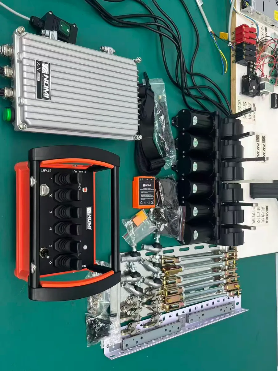
Record the findings before approving a retrofit design. Photographs are particularly useful when they show the existing control panel, valve assembly, component labels, wiring interfaces, and available receiver mounting locations.
A photograph helps identify the arrangement, but it should not replace a wiring diagram, electrical measurement, or confirmed component specification.
Conditions that require further engineering review
Not every hydraulic machine is a suitable candidate for a straightforward retrofit.
Pause the installation design if the existing equipment has undocumented electronic controls, damaged wiring, unidentified valve interfaces, modified safety circuits, or an unclear relationship between the proposed remote and the original controls.
A machine may also require a more extensive redesign if a proposed control change affects load holding, braking, steering, machine stabilization, or an OEM-specific controller.
In these circumstances, the next step is to obtain the relevant diagrams and manufacturer information, then assess the complete control architecture. Replacing the remote transmitter alone will not resolve an underlying hydraulic or electrical defect.
Read more: How to Choose a Wireless Remote Control for Hydraulic Machinery.
2. Prepare the Installation Package Before Work Begins
The most useful installation document is not simply a list of components. It is a machine-specific record showing how each requested operator command will be translated into a machine action.
Prepare the following documents before the installation team starts work:
-
An existing-system diagram, including the known electrical and hydraulic interfaces.
-
A proposed connection diagram for the transmitter, receiver, power supply, and controlled components.
-
A control-function map identifying every button, joystick axis, selector, enable device, and intended machine movement.
-
A description of the required stop, emergency-stop, communication-loss, startup, and restart behavior.
-
A site-specific risk assessment and an approved method for isolating hazardous energy.
-
An acceptance-test plan defining the test conditions, expected outcomes, and records required for release.
The function map deserves particular attention. Labels such as “Function 1” and “Function 2” are not sufficient for commissioning unless they are tied to defined machine movements.
For example, a crane installation could document a function as follows:
| Item | Example of a useful record |
|---|---|
| Operator input | Joystick axis assigned to boom movement |
| Intended action | Boom raises when the input is moved in the specified direction |
| Controlled interface | Confirmed receiver output and compatible valve-control interface |
| Operating mode | Proportional or on/off, as designed |
| Neutral behavior | Defined by the approved control design |
| Verification | Actual movement matches the function map under the approved test conditions |
The example illustrates how to document a function. It does not specify the wiring or joystick direction for any particular crane.
For machines requiring multiple motions, prepare the complete function map before assigning receiver outputs. That makes it easier to identify duplicated assignments, reversed directions, missing interlocks, and conflicts between controls before they affect the machine.
3. Choose the Appropriate Installation Architecture
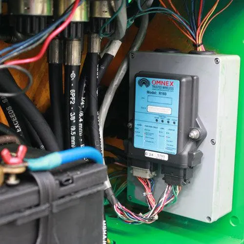
The installation method depends on the interface available on the existing machine, rather than on the number of controls on the transmitter alone.
Three broad retrofit approaches are common.
| Approach | Typical arrangement | Main engineering consideration |
|---|---|---|
| Electrically actuated hydraulic valves | The receiver controls compatible electrically operated valves or actuators | Valve compatibility, coil specifications, output ratings, and hydraulic behavior |
| Existing electronic controller | The receiver provides commands to a controller that manages machine functions | Supported inputs, software configuration, command authorization, and safety logic |
| Proportional control interface | The transmitter’s variable command is converted into a compatible proportional control signal | Signal type, scaling, neutral point, ramp behavior, and valve response |
These are architectural categories, not a declaration that a particular machine supports every option.
Direct valve control is not always appropriate
A receiver output may be intended for a particular voltage, current, or signal type. A valve coil may require different electrical characteristics, while a proportional valve may require an amplifier or a controller-generated command.
Connecting components based only on a matching connector, wire color, or nominal voltage can damage equipment or produce unpredictable movement.
The engineering package should identify the exact receiver output specification and the receiving component’s input requirements. Protection, suppression, signal conditioning, and isolation must be considered where required by the component manufacturers and the system design.
Proportional control requires additional validation
A proportional joystick typically represents a variable command, while an on/off control provides a discrete command. When retrofitting a proportional arrangement, correct movement direction is only one part of commissioning.
The team must also verify the neutral point, deadband, command scaling, ramp behavior, and actuator response in accordance with the relevant manuals and design requirements. An incorrect neutral setting may cause unwanted movement, while incorrect scaling may produce a response that differs significantly from the operator’s intended input.
For applications involving continuous speed adjustment, Nomi’s joystick remote controls are one product category to evaluate against the machine’s control-interface requirements.
For defined switching functions, push-button remote controls may be a more appropriate starting point. Neither configuration should be considered compatible until the complete interface and safety requirements have been confirmed.
4. Install the Receiver and Complete the Electrical Integration
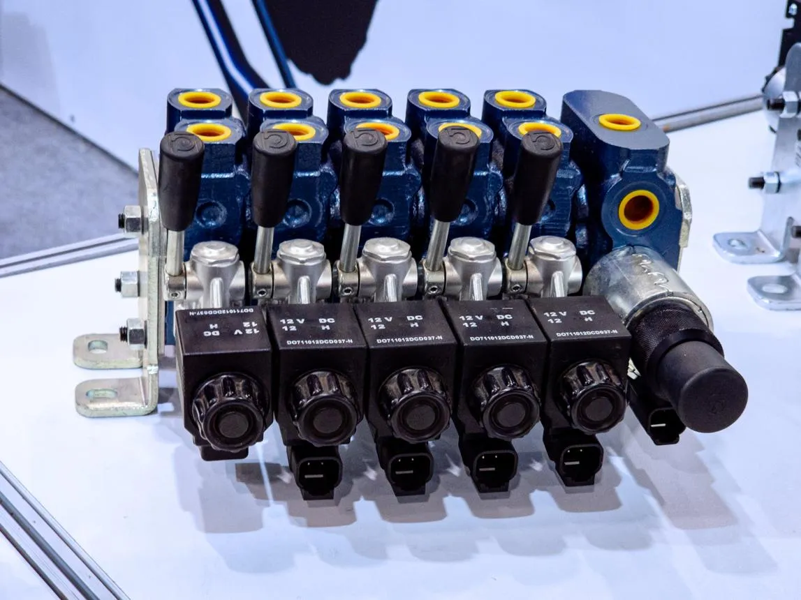
Receiver installation should follow the manufacturer’s instructions for the specific model. The enclosure, antenna arrangement, supply requirements, connectors, and permissible mounting conditions can differ between systems.
Select a suitable receiver location
Assess the mounting location before drilling or fabricating brackets.
The selected position should provide the specified environmental protection, secure mechanical support, access for inspection, and adequate clearance for cables and connectors. It should also account for vibration, impact, heat, water exposure, contamination, and the possibility of maintenance tools damaging the enclosure.
A metal enclosure or surrounding structure may affect radio propagation. A mounting position that is convenient for wiring may therefore be unsuitable for communication. Follow the manufacturer’s antenna and receiver placement requirements rather than assuming that the enclosure can be mounted anywhere on the machine.
Cable routing should prevent abrasion, crushing, excessive bending, and interference with hot or moving parts. Connectors must be installed and sealed as instructed, with strain relief where specified.
Do not drill into a structural member, open a sealed enclosure, or modify an antenna arrangement without confirming that the change is permitted by the relevant design requirements.
Verify the power supply and protection
Measure or otherwise confirm the actual supply characteristics against the receiver’s documentation. The machine’s nominal electrical-system voltage alone does not establish that a receiver can be powered safely from a particular connection.
Check the requirements for:
-
Operating voltage and permissible supply variation.
-
Available current and any startup or transient requirements.
-
Fuse or circuit-breaker selection, where specified.
-
Polarity, grounding, and electrical protection.
-
Separation or routing requirements for power, control, and communication wiring.
-
Connector assignments and terminal identification.
Use the approved wiring diagram and terminal designations. Never infer a terminal’s function from its physical position or a wire’s color alone.
The applicable electrical requirements should be confirmed for the installation location and machine category. The IEC 60204-1 machinery electrical-equipment standard covers relevant general requirements for machine electrical equipment, including control-circuit and technical-documentation considerations. Its applicability and the appropriate edition must be assessed for the actual project.
Integrate with the existing machine controls
Where the wireless receiver interfaces with an existing controller, confirm which input types, signal ranges, communication protocols, and command conditions the controller actually supports.
Where the receiver drives an electrical valve interface, verify the complete relationship between output and load, including the relevant voltage, current, and control method.
If the original operator controls will remain available, document when and how each control source is permitted to operate. The design must prevent conflicting commands or ambiguous authority over machine motion.
Retaining original controls may be possible in some retrofits, but it must be an intentional, verified part of the control design. It should not be assumed that an untouched manual lever automatically remains safe after an electrical modification.
Read more: How to Make Remote Control Hydraulic Excavators: Retrofit Real Units.
5. Complete Hydraulic Integration Without Compromising the Existing Circuit
An important retrofit decision is whether the existing hydraulic valves can remain in place or whether a valve-interface modification is needed.
Start with the actual valve documentation and machine schematic. Identify the control method, valve model, relevant electrical or mechanical interface, and any requirements for holding, braking, or controlled movement.
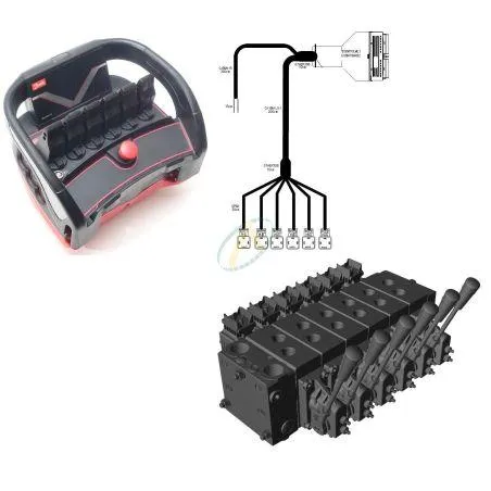
If electrically actuated valves or replacement coils are proposed, confirm their compatibility with the existing valve assembly. A similar-looking coil or a connector that fits physically does not establish that its electrical characteristics or mechanical interface are correct.
Hydraulic modifications should be kept within the approved scope of work. Do not change pressure settings, bypass protective devices, alter load-holding arrangements, or modify hydraulic lines merely to make the wireless controls function.
Before disturbing a hydraulic component, follow the machine manufacturer’s safe isolation and pressure-relief procedure. A stopped engine or de-energized receiver does not necessarily mean the hydraulic system is free from stored energy.
Account for stored energy and suspended loads
Hydraulic machinery can retain energy in pressurized circuits, accumulators, elevated structures, or loaded actuators. Gravity and mechanical spring forces may remain hazardous even after the machine’s primary power source has been switched off.
The installation plan must identify these hazards and specify the required isolation, mechanical support, pressure relief, and verification procedures.
OSHA’s Control of Hazardous Energy regulation, 29 CFR 1910.147 sets out requirements relevant to hazardous-energy isolation during servicing and maintenance in its jurisdiction. The applicable local regulations and the equipment manufacturer’s procedures must also be followed.
This is an important distinction: wireless-control wiring and hydraulic work may be related within the same project, but they require different technical checks and safety precautions.
6. Configure the Transmitter and Receiver
Once the hardware interfaces have been installed and checked, configure the transmitter and receiver according to their specific operating instructions.
The exact sequence depends on the product. Some systems require a pairing or address-setting procedure. Others require channel assignment, parameter configuration, or integration with the machine’s existing controller.
Do not assume that a general transmitter-receiver pairing procedure applies to every wireless system.
Verify command assignments
Use the approved function map to verify that each control operates only its assigned function.
For multi-axis joysticks, verify each axis independently. Confirm direction, neutral response, proportional behavior where applicable, and any intended restrictions on simultaneous operation.
For push-button systems, verify the action associated with each control, including any start, enable, selector, or mode functions. Controls that change operating modes must be clearly documented so that the operator understands which command set is active.
Check startup and restart behavior
The machine should not begin moving unexpectedly when the transmitter is switched on, when the receiver regains power, or when communication is re-established.
The required behavior must be established by the control-system design and risk assessment. Depending on the system, this can involve neutral-position checks, a deliberate start sequence, an enable action, or other controls designed to prevent unintended motion.
The team should specifically check what happens when the transmitter is turned off and on, when the receiver is power-cycled, and when a fault is cleared.
Resetting an emergency stop or restoring communication must not be treated as automatic permission to restart hazardous movement.
7. Commission the System Using a Defined Acceptance-Test Plan
Commissioning is the point at which the completed installation is compared with the documented requirements. A transmitter that communicates with a receiver is not, by itself, evidence that the installation is correct.
Testing must be conducted by qualified personnel using the approved test plan, with the machine in a controlled condition and the test area managed so that people are not exposed to hazardous movement.
Where initial motion tests are necessary, follow the machine-specific procedure for establishing a safe test condition. Do not conduct live functional testing while personnel are exposed to uncontrolled hydraulic movement, suspended loads, or other hazards.
Recommended commissioning test matrix
| Test | What to verify | Evidence to record |
|---|---|---|
| Power-up | Receiver and transmitter start as specified, with no unexpected machine movement | Startup observations and any fault indications |
| Pairing and authorization | The intended transmitter controls the intended receiver, as designed | Pairing result and system identification |
| Function mapping | Each input produces its assigned machine response | Completed function-by-function test record |
| Direction | Each movement follows the approved function map | Verified input and corresponding movement |
| Neutral and release behavior | Releasing a control produces the specified response | Observed response and acceptance result |
| Proportional behavior | Variable commands produce the specified control response where proportional control is used | Calibration record and relevant observations |
| Normal stop | The normal stopping command behaves as designed | Test conditions and observed stopping behavior |
| Emergency stop | The emergency-stop function achieves the required machine-level safe response | Test result and required reset behavior |
| Communication loss | The machine responds as specified when valid communication is lost | Test method and measured or observed result |
| Power interruption and recovery | Loss and restoration of power do not cause unintended motion | Observations of shutdown and restart behavior |
| Operating boundary | Communication is reliable within the intended operating area under relevant conditions | Test locations, conditions, and findings |
| Existing controls and interlocks | The modified system does not introduce conflicting controls or defeat required protections | Inspection findings and functional test results |
The table is a framework for building a project-specific acceptance test. It does not establish universal pass criteria, response times, operating distances, or safety performance levels. Those must come from the applicable design, product documentation, machine requirements, and risk assessment.
Validate communication-loss behavior carefully
The expected response to loss of communication deserves particular attention.
For some machines, the intended response may be to stop a motion and maintain the position. For others, simply de-energizing an output could introduce a different hazard, such as loss of load holding or an uncontrolled movement. The correct response depends on the machine’s design and the relevant risk assessment.
Accordingly, test the complete machine response, not just whether the receiver’s output switches off.
For relevant overhead and gantry cranes in the United States, OSHA’s 29 CFR 1910.179 includes a requirement for remotely operated cranes to stop crane motion if the control signal becomes ineffective. Other machinery and jurisdictions may have different or additional requirements.
For earth-moving machinery, ISO 15817:2012, Safety requirements for remote operator control systems, is a relevant reference for the remote-control safety requirements within its defined scope. It should not be assumed to cover every type of hydraulic machine.
Test emergency-stop behavior as a machine-level function
An emergency-stop button on a transmitter is not sufficient evidence that the complete machine has a compliant emergency-stop function.
The installation must establish how the emergency-stop command is transmitted, interpreted, and acted upon by the machine’s control architecture. It must also verify the machine’s resulting state and the conditions under which operation may resume.
An emergency stop, a normal stop command, and communication-loss behavior are distinct conditions. They must not be treated as interchangeable merely because all three can result in halted motion.
The relevant emergency-stop principles and electrical control requirements should be established from the applicable machine standards and the approved safety design. For control systems that perform safety functions, ISO 13849-1:2023 provides a methodology for designing and integrating safety-related parts of control systems. The required safety functions and performance levels must be determined for the specific application rather than assumed from a component’s product description.
Evaluate radio performance in the actual operating area
A successful test at the receiver’s mounting location does not establish reliable communication throughout the machine’s intended working area.
The test should reflect the real installation, including the operator’s working positions, relevant machine orientations, surrounding structures, and likely sources of interference.
Record the conditions and locations tested. Compare the results with the manufacturer’s specified operating conditions and the project’s acceptance criteria.
If communication is unstable, investigate the installation, antenna arrangement, environmental conditions, interference, and system configuration. Do not simply declare a larger operating distance acceptable or change radio settings without confirming the manufacturer’s instructions and applicable radio regulations.
For construction cranes and other equipment with defined operating areas, the test should cover the positions and operating conditions that matter to the actual task. Nomi’s construction crane remote controls provide an application-specific product reference, but the final acceptance criteria must remain machine-specific.
8. Resolve Installation Problems Before Returning the Machine to Service
The following table links common commissioning symptoms to reasonable diagnostic starting points. These are diagnostic hypotheses, not definitive diagnoses.
| Observed symptom | Possible causes to investigate | Appropriate next step |
|---|---|---|
| Receiver does not power up | Incorrect supply, polarity error, open circuit, protective device operating, or faulty connection | Isolate as required and verify the supply and connections against the wiring diagram |
| Transmitter cannot control the receiver | Pairing or addressing problem, incorrect configuration, inadequate power, or radio interference | Follow the product manual’s pairing procedure and confirm system identification |
| A movement operates in the wrong direction | Function assignment error, incorrect wiring, or inconsistent configuration | Stop functional testing and correct the mapping according to the approved diagram |
| A control has no effect | Incorrect assignment, incompatible input or output, wiring fault, interlock condition, or a machine-side fault | Trace the command path systematically without bypassing safety functions |
| Proportional motion is uneven or unexpected | Incorrect neutral, scaling, signal configuration, calibration, or hydraulic response | Compare configuration and measurements with the specified input-output relationship |
| Communication becomes intermittent | Antenna installation, shielding, obstructions, interference, power stability, or damaged components | Inspect the installation and repeat the site test after correcting the identified cause |
| Original controls conflict with the wireless system | Incorrect integration, an undefined control-source priority, or a design limitation | Return to the control architecture and establish an approved operating arrangement |
| Emergency stop or restart behavior is incorrect | Control integration or safety-logic fault | Keep the machine out of normal operation until the issue is resolved and the relevant function is retested |
Do not bypass an interlock, bridge a safety input, increase a protective setting, or repeatedly reset a fault simply to complete commissioning. If a test produces an unexpected response, record the result, place the equipment in the required safe condition, and investigate the cause before continuing.
For more complex problems, use the appropriate manuals for the transmitter, receiver, valve interface, and machine controller. Each subsystem may be functioning as designed while the integrated system is still configured incorrectly.
9. Document the Modification and Hand Over the Machine
The installation is not complete when the final movement test succeeds. The completed system must also be documented so that operators, maintenance personnel, and future technicians can understand the modified control arrangement.
Prepare a handover package containing the relevant records:
| Document | What it should contain |
|---|---|
| As-built wiring diagram | Actual connections, component identification, and receiver output assignments |
| Updated control-function map | Final input assignments and corresponding machine actions |
| Component information | Transmitter, receiver, valve interface, controller, and relevant component identification |
| Configuration record | Approved settings and any calibration information required for maintenance |
| Commissioning report | Tests performed, conditions, results, deviations, and corrective actions |
| Safety documentation | Applicable risk assessment, safety-function verification, and relevant conformity or compliance documentation |
| Operating instructions | Startup, normal operation, stop, emergency-stop, shutdown, and approved response to faults |
| Maintenance instructions | Inspection requirements, battery care where applicable, and manufacturer-specified service procedures |
| Training record | Confirmation that authorized operators and maintainers have received the required instruction |
Do not create a declaration of conformity or claim certification simply because a retrofit has been completed or tested. Whether a modification affects the machine’s conformity obligations depends on the machine, the nature of the modification, and the applicable jurisdiction.
For machines supplied or modified for different markets, the project team should identify the relevant legal requirements and standards before deciding which documents are necessary.
Train operators on the modified controls
A familiar machine can behave differently after a control retrofit, even when its hydraulic actuators and principal functions remain unchanged.
Operator training should explain the actual transmitter layout, the mapping between inputs and movements, the startup sequence, the machine’s stopping behavior, emergency-stop use, and what to do if communication or control becomes unreliable.
Operators must also understand the permitted working area, visibility requirements, relevant exclusion zones, and any limitations established by the machine-specific risk assessment.
Only authorized personnel should operate the modified system. The machine should be released for normal use after the required commissioning, safety verification, documentation, and handover activities have been completed.
10. When Should a Wireless Remote Control Retrofit Be Delayed or Reconsidered?
A retrofit should be delayed when its compatibility or safety cannot be established with sufficient confidence.
Further engineering work may be necessary when the machine’s hydraulic circuit is poorly documented, electrical components are obsolete, or the receiver cannot interface with the existing controller using a supported method.
The same applies when the proposed installation would interfere with a required safety function, create ambiguity between two control stations, compromise load holding, or introduce an unacceptable startup or communication-loss condition.
Environmental and regulatory restrictions may also affect feasibility. A remote-control product suitable for one site may not be suitable for another site with different radio requirements, hazardous-area conditions, or environmental exposure.
A technically successful radio connection is therefore only one acceptance criterion. The retrofit must work as part of the complete machine and remain appropriate for its intended use.
Questions to resolve before approving the retrofit
Before authorizing the final installation, the project team should be able to answer these questions:
-
Is the existing hydraulic and electrical architecture sufficiently documented to design the interface?
-
Are the receiver outputs and machine inputs confirmed to be compatible?
-
Has the required relationship between wireless commands and original controls been established?
-
Are normal stopping, emergency stopping, power interruption, and communication-loss responses defined and verified?
-
Has the actual operating environment been considered in receiver placement and radio testing?
-
Have the applicable safety requirements and modification obligations been identified?
-
Are the commissioning results, updated diagrams, and operator instructions available for handover?
Unresolved answers should become explicit engineering actions, not assumptions carried into the installation.
For a retrofit inquiry, Nomi’s industrial hydraulic remote-control systems are a relevant starting point. Sharing the machine model, photographs of the existing controls and valve assembly, available wiring diagrams, supply details, required functions, and country of installation will help establish what needs to be reviewed before a configuration is proposed.
Technical information can be submitted through the Nomi contact page.
A successful retrofit is not defined simply by whether a transmitter can move the machine. It is defined by whether the new control arrangement is compatible with the equipment, behaves as intended under normal and abnormal conditions, and can be operated and maintained using verified documentation.
FAQ
1. Can any hydraulic machine be converted to wireless remote control?
No. Retrofit feasibility depends on the existing control architecture, the hydraulic valve interface, electrical supply, available controller inputs, and safety requirements. Some machines can accept a relatively straightforward electrical-control modification, while others require additional engineering or may not be suitable for the proposed retrofit.
2. Does a wireless hydraulic remote control retrofit require replacing the existing hydraulic valves?
Not necessarily. Existing valves may remain in place if a compatible control interface is available. Replacement or additional components may be needed when the existing valves do not support the required electrical actuation or when the proposed system requires a different control method. The valve model and manufacturer documentation should be checked before installation.
3. Can the original manual controls remain operational after a wireless retrofit?
Sometimes, but this must be established by the control-system design. The relationship between manual and wireless controls must be defined so that conflicting commands and unintended movement are prevented. The retained controls must also remain consistent with the machine’s safety requirements.
4. How long does industrial wireless remote control installation take?
Installation time varies with machine complexity, valve accessibility, wiring conditions, the number of controlled functions, and the required safety-system modifications. The time needed for commissioning and documentation must also be included. A reliable estimate requires a review of the actual machine and installation scope.
5. Can a wireless remote control provide proportional hydraulic movement?
Yes, when the transmitter, receiver, hydraulic valve interface, and any required controller or amplifier support proportional operation. Commissioning should verify neutral position, command scaling, movement direction, and response throughout the required operating range. An ordinary on/off interface cannot automatically provide proportional control.
No. The emergency-stop function must be integrated into the complete machine-control architecture and verified against the applicable requirements. The machine’s stopping behavior, safety logic, reset conditions, and response to relevant faults must all be considered. A transmitter feature alone does not establish system-level compliance.
7. How should communication-loss behavior be verified after installation?
The commissioning plan should define the required machine response, the conditions for triggering communication loss, and the acceptance criteria. Tests should verify the complete machine response rather than checking only a receiver output. Particular care is required for machines where uncontrolled movement or loss of load holding could create a hazard.
8. What information should be sent to a supplier before requesting a retrofit quotation?
Provide the machine manufacturer and model, photographs of the existing controls and valve assembly, available hydraulic and electrical diagrams, power-supply details, the functions to be controlled, proportional or on/off requirements, the operating environment, and the country of installation. Identify any known limitations or existing controller requirements as well.
9. What documents should be retained after the retrofit?
Retain the as-built wiring diagram, final function map, component identification, relevant configuration records, commissioning report, safety documentation, updated operating instructions, and operator-training records. Include any other documents required by the machine manufacturer or applicable regulations.
