

A universal remote control hydraulic kit is not necessarily compatible with every hydraulic machine. The best kit is the one that matches the machine’s existing hydraulic control architecture, electrical interface, operating functions, and safety requirements. A simple wireless kit may be sufficient for a hydraulic power unit that only needs raise and lower commands, while a crane, loader, or other multi-function machine may require proportional joysticks, a programmable receiver, compatible valve drivers, or external actuators.
Before purchasing a hydraulic wireless remote control kit, buyers should identify what the system actually needs to control. The transmitter and receiver are only part of the solution. The connection between the receiver and the machine’s hydraulic control system determines whether the kit can operate the equipment correctly.
1. What Is a Universal Remote Control Hydraulic Kit?
A universal remote control hydraulic kit is a collection of wireless control components intended to operate hydraulic equipment without requiring the operator to remain beside the machine’s original control panel or mechanical levers.
Depending on its design, a kit can transmit simple switching commands or proportional movement commands to an existing electro-hydraulic control system.
The word “universal” is often used in product descriptions, but it needs to be interpreted carefully. A kit may work with several models of hydraulic power units while remaining incompatible with other valve arrangements, electrical systems, or control protocols.
For example, a two-function transmitter designed for a dump trailer hydraulic power unit cannot automatically replace a multi-axis proportional remote control on a truck-mounted crane.
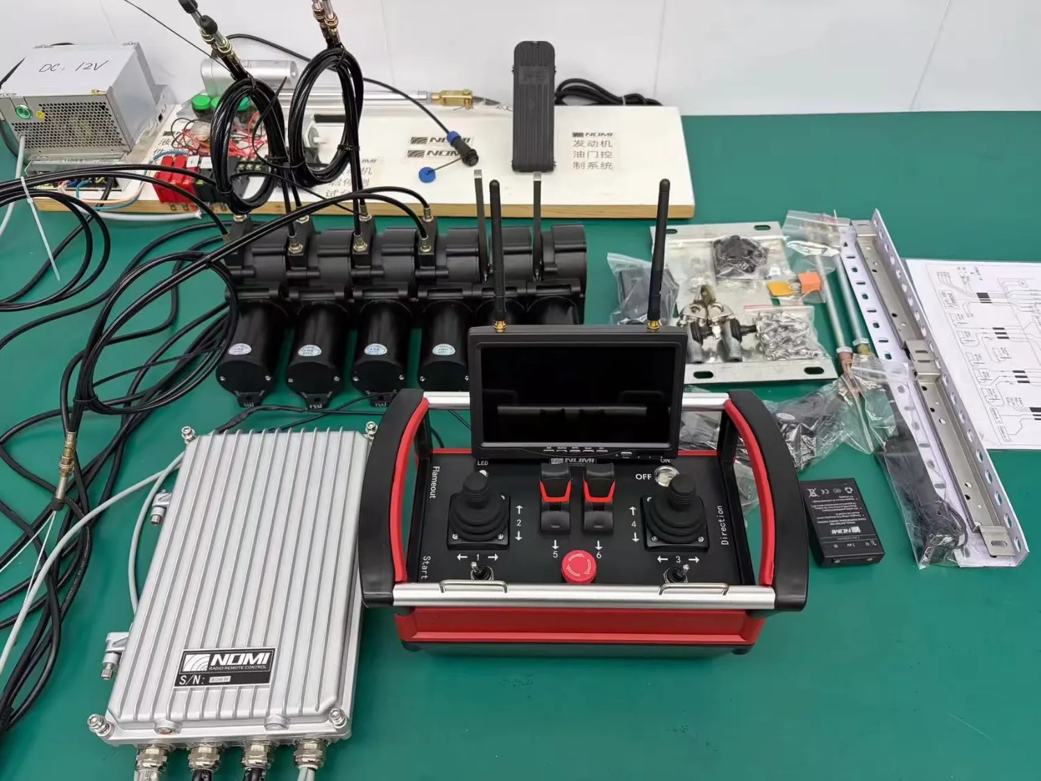
1.1 What components should a complete kit include?
The actual contents depend on the control architecture and the scope of the retrofit.
| Component | Main purpose | What buyers should verify |
|---|---|---|
| Wireless transmitter | Sends operator commands | Joystick axes, switches, buttons, operating layout |
| Wireless receiver | Receives and processes commands | Supported outputs, pairing, communication behavior |
| Antenna | Supports radio communication | Antenna type, mounting position, cable arrangement |
| Electrical harness | Connects the receiver to machine controls | Pinout, connector, wire specification, protection |
| Output drivers | Convert control commands into suitable electrical signals | Voltage, current, PWM or analog requirements |
| Proportional valve interface | Controls variable hydraulic movement | Valve type, amplifier compatibility, command characteristics |
| External actuators | Operate existing mechanical valve levers when required | Travel, force, mounting, alignment, return behavior |
| Emergency-stop components | Implement the machine’s required emergency-stop function | Safety architecture and integration requirements |
| Power and charging components | Supply the transmitter and receiver | Battery type, charger, supply voltage |
| Technical documentation | Supports installation and maintenance | Wiring diagram, configuration details, operating instructions |
Not every kit needs every component.
A wireless receiver connected to an existing proportional electronic valve may not need external mechanical actuators. A retrofit that retains a manually operated valve bank may need motorized or servo-based actuators. A basic hydraulic power unit kit may contain only a transmitter, receiver, and wiring harness.
This distinction matters when comparing quotations. Two suppliers may both advertise a complete hydraulic remote control kit but include substantially different hardware.
1.2 Does the kit include the hydraulic valve?
This is one of the first questions to ask.
A wireless remote control system does not automatically include a new hydraulic valve, hydraulic pump, or power unit.
There are three common arrangements:
- Electronic retrofit: The receiver connects to the machine’s existing solenoid valves, proportional valve amplifiers, or electronic controller.
- Mechanical retrofit: External actuators move the machine’s existing manual valve levers.
- Hydraulic system replacement or modification: The project includes additional hydraulic valves, pilot components, wiring, and potentially changes to the hydraulic circuit.
A quotation should explicitly state which arrangement is being supplied.
If a supplier offers only a transmitter and receiver, the buyer must confirm who is responsible for the remaining electrical and hydraulic integration.
2. Five Types of Hydraulic Remote Control Kits and Their Compatibility
There is no single control architecture suitable for every hydraulic application. The following five categories represent practical approaches found in the industrial remote-control market.
2.1 Wireless kits for hydraulic power units
These are among the simplest solutions.
They are commonly used for equipment where the hydraulic system performs a limited number of clearly defined actions, such as raising and lowering a dump body or operating a small hydraulic lifting mechanism.
A typical arrangement includes:
- A handheld wireless transmitter.
- A receiver with switching outputs.
- An electrical harness.
- Connections to the hydraulic power unit’s control circuit.
The receiver activates the appropriate solenoid or relay according to the selected command.
Some products support different single-acting and double-acting power-unit configurations, but compatibility still depends on the manufacturer’s specified wiring and electrical arrangement.
For example, the Maxim two-function hydraulic pump remote illustrates a product designed specifically for hydraulic power-unit operation rather than general-purpose proportional machinery control.
Best suited for:
- Dump trailers.
- Simple hydraulic lifting systems.
- Hydraulic power packs.
- Equipment requiring a small number of on/off functions.
Limitations:
A basic raise/lower kit is not a replacement for a proportional multi-axis remote control. It generally does not provide the variable-speed control required for sophisticated machine movements.
Buyers should also check whether the receiver is compatible with the existing pump controller, solenoid arrangement, and wiring harness.
2.2 Wireless kits for solenoid-operated hydraulic valves
Some machines use electrically operated directional control valves.
In this architecture, the receiver controls electrical signals connected to the valve solenoids. Depending on the valve configuration, the system may activate one or more outputs to select different hydraulic movements.
The main benefit is that the existing valve bank can potentially remain in place.
However, a solenoid valve is not automatically compatible with every wireless receiver.
The following electrical characteristics should be checked:
- Nominal coil voltage.
- Coil current and power requirements.
- Number of solenoid coils.
- Connector and pin arrangement.
- Output polarity and switching configuration.
- Whether the valve is on/off or proportional.
- Whether an external driver or amplifier is required.
For example, a receiver with relay outputs may be suitable for switching a compatible solenoid circuit, but it should not be assumed to provide the regulated current required by a proportional valve.
The correct connection depends on the valve manufacturer’s technical specifications.
Best suited for: Machines with existing solenoid-operated directional valves and clearly defined switching functions.
Not necessarily suitable for: Equipment requiring smooth variable-speed control when the receiver offers only on/off outputs.
2.3 Proportional hydraulic remote control kits
For industrial machinery requiring controlled variable movement, a proportional wireless remote control system is often more appropriate.
A proportional joystick allows the operator to command different movement levels rather than simply switching a function on or off.
For example, moving a joystick a short distance may request a relatively low actuator speed, while moving it farther may request a greater control output.
The receiver processes this command and supplies an appropriate signal to the machine’s control system.
Depending on the application, the interface may involve:
- Analog voltage outputs.
- Current-controlled proportional outputs.
- PWM signals.
- Ratiometric signals.
- Controller communication interfaces such as CAN.
These signal types are not interchangeable. The signal expected by the valve amplifier or machine controller must match the output provided by the receiver.
A proportional system may also require calibration, including neutral position, output limits, movement direction, ramp settings, and valve response.
Best suited for:
- Truck-mounted cranes.
- Construction machinery.
- Forestry loaders.
- Concrete pump trucks.
- Industrial hydraulic systems requiring variable-speed movement.
- Equipment requiring controlled acceleration and deceleration.
Main purchasing consideration:
Do not select a proportional receiver simply because it advertises analog outputs. Confirm the output characteristics, the valve amplifier requirements, and whether the machine’s control system accepts the proposed signal.
2.4 External actuator retrofit kits for manual hydraulic valve banks
Some hydraulic machines still rely on manually operated directional valve levers.
In these cases, adding an ordinary electronic receiver does not solve the problem because the machine does not have the electrical control interface required by the receiver.
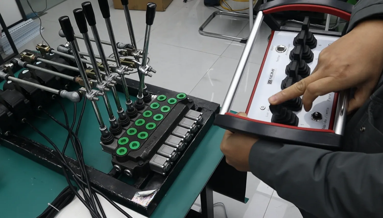
One possible retrofit approach is to install external electromechanical actuators that move the existing valve levers.
A wireless transmitter sends the command, the receiver controls the actuators, and the actuators mechanically move the valve spools through the original lever mechanisms.
This approach can preserve the existing valve bank and may reduce the need for extensive hydraulic circuit modifications.
A practical example is the HOVST Pro-X4 manual valve retrofit kit, which uses external actuators to operate a four-spool manual valve bank.
Before selecting this architecture, verify:
- The number of valve spools that need remote operation.
- The lever travel required for each direction.
- The force needed to move each lever.
- The available mounting space.
- Whether the actuators can return to the required neutral position.
- Whether original manual controls remain accessible.
- Whether simultaneous functions are required.
- Whether the actuator arrangement is protected against vibration, dirt, and water exposure.
The mechanical interface is especially important.
Two valve banks with the same number of spools may have different lever shapes, mounting dimensions, travel distances, and operating forces.
Consequently, spool count alone does not establish mechanical compatibility.
Best suited for: Existing manual hydraulic valve systems where preserving the original valve bank is preferable to replacing the control architecture.
Limitations: Mechanical mounting, actuator force, alignment, and valve-specific behavior may require a customized installation.
2.5 CAN-based and integrated electronic control systems
Modern mobile machinery may use electronic controllers to coordinate engine functions, hydraulic movements, interlocks, and auxiliary equipment.
In these cases, the remote-control system may need to communicate with an existing machine controller instead of directly driving individual valve coils.
CAN communication, including SAE J1939-based systems, may be used in some applications.
A compatible system must consider more than the physical CAN connection.
The integration process may involve:
- Supported communication protocol.
- Message identifiers.
- Signal definitions.
- Scaling and command limits.
- Update frequency.
- Communication timeout behavior.
- Diagnostic information.
- Machine-specific interlocks.
- Priority between remote commands and existing controls.
The Anderson Controls two-joystick radio system provides an example of an industrial radio receiver offering multiple configurable output types, including proportional, switching, and CAN-based I/O.
Best suited for: Equipment with an established electronic control architecture.
Limitations: A CAN connection does not guarantee that two devices can communicate correctly. The relevant protocol, message definitions, software configuration, and machine safety logic must be verified.
3. Hydraulic Remote Control Kit Compatibility: What Actually Determines Whether It Fits?
The most reliable way to determine compatibility is to examine the complete control path from the operator’s command to the hydraulic actuator.
A simplified system can be represented as:
Operator → Wireless transmitter → Radio communication → Receiver → Electrical or mechanical interface → Hydraulic control valve → Hydraulic actuator
Every connection in this chain must perform its intended function.
A transmitter may communicate correctly with its receiver while the receiver remains incompatible with the machine’s valve or controller.
The following compatibility checks should be completed before ordering.
3.1 Identify the existing hydraulic control architecture
First, determine how the machine currently controls its hydraulic movements.
| Existing machine arrangement | Potential remote-control approach | Main compatibility requirement |
|---|---|---|
| Manual directional valve | External actuator retrofit | Lever geometry, force, and travel |
| Solenoid directional valve | Receiver with compatible switching outputs | Coil voltage, current, and wiring |
| Proportional electro-hydraulic valve | Proportional receiver and suitable driver | Signal characteristics and valve calibration |
| Hydraulic pilot control | Compatible pilot-control interface | Pilot circuit and control arrangement |
| ECU or PLC-based control | Programmable electronic receiver | Controller interface and communication logic |
| Mixed manual and electronic controls | Hybrid configuration | Function mapping and control priority |
The machine’s model name is useful, but it is not sufficient on its own.
Different production years, optional configurations, and control-system revisions may use different components.
A supplier should ideally review the machine’s actual valve and electrical configuration.
3.2 Check the electrical supply
Industrial hydraulic equipment may use different electrical supply arrangements.
For example, 12 VDC and 24 VDC are common in mobile machinery, but they should not be treated as universal values.
Confirm:
- Nominal operating voltage.
- Permitted voltage variation.
- Startup and transient conditions.
- Available current capacity.
- Positive and negative connections.
- Grounding arrangements.
- Fuse and circuit protection.
- Power supply for the receiver and any external drivers.
A receiver rated for a particular nominal voltage is not necessarily compatible with an electrical system experiencing voltage conditions outside its specified operating range.
The same applies to proportional valve outputs. Matching the receiver’s supply voltage does not establish that its output can drive the valve correctly.
3.3 Verify valve input and output compatibility
This is often the most important technical step in an electronic retrofit.
A hydraulic directional valve may use a simple switching coil, a proportional solenoid, or another manufacturer-specific control arrangement.
The receiver output must be appropriate for the connected device.
| Output type | Typical control role | Important verification |
|---|---|---|
| Relay output | Switching a compatible electrical circuit | Contact rating and load type |
| Digital output | Discrete machine commands | Voltage level and current capacity |
| Analog voltage | Variable control signal | Voltage range, reference, and scaling |
| Current-controlled output | Proportional valve command | Required current range and driver characteristics |
| PWM output | Electronic control signal | Frequency, duty cycle, and electrical interface |
| Ratiometric output | Variable signal relative to a reference supply | Reference voltage and signal scaling |
| CAN interface | Communication with an electronic controller | Protocol and message definitions |
These are examples of control-interface categories, not a statement that every hydraulic remote receiver supports all of them.
Before purchasing, ask the supplier to identify the exact receiver output assigned to each machine function.
3.4 Count hydraulic functions correctly
A common purchasing mistake is to count buttons rather than actual machine movements.
Consider a machine with four hydraulic functions:
- Boom up and down.
- Boom extension and retraction.
- Winch lifting and lowering.
- Auxiliary hydraulic movement.
The four functions may require different control arrangements.
Some may need proportional joystick control. Others may only need on/off switching.
A two-axis joystick can control two independent axes, with each axis normally supporting movement in opposite directions. Additional buttons may control auxiliary functions.
However, the number of buttons, joystick axes, hydraulic valve sections, and independently controlled machine functions are not necessarily the same.
Before selecting a transmitter, prepare a function table.
| Machine function | Desired operation | Control requirement |
|---|---|---|
| Boom lifting | Raise and lower | Proportional |
| Boom extension | Extend and retract | Proportional |
| Winch | Lift and lower | Proportional or application-specific |
| Horn | Activate and release | On/off |
| Engine speed | Increase and decrease | Depends on engine interface |
| Auxiliary function | Activate and release | On/off or proportional |
The supplier can then determine an appropriate transmitter layout and receiver output configuration.
3.5 Consider the hydraulic circuit only where the retrofit affects it
Not every wireless remote-control purchase requires a complete hydraulic circuit redesign.
If the kit only interfaces with an existing electrical valve controller, the receiver may not need direct access to the hydraulic pressure and flow specifications.
However, if the project includes additional hydraulic valves, pilot components, or changes to the hydraulic circuit, further information becomes essential.
Depending on the design, check:
- Maximum working pressure.
- Required flow rate.
- Valve center configuration.
- Hydraulic port sizes.
- Cylinder and hydraulic motor characteristics.
- Load-holding requirements.
- Pressure relief arrangements.
- Return-line and filtration requirements.
A radio receiver cannot compensate for an incorrectly sized hydraulic valve or an unsuitable hydraulic circuit.
It is important to separate wireless control compatibility from hydraulic performance compatibility.
4. Which Hydraulic Remote Control Kit Is Best for Different Machines?
The best solution depends on what the machine needs to accomplish.
The following table provides a practical starting point rather than a universal compatibility guarantee.
| Application | Potentially suitable kit | Important consideration |
|---|---|---|
| Dump trailer | Hydraulic power-unit wireless kit | Pump and solenoid arrangement |
| Small hydraulic lifting equipment | On/off or proportional system | Whether controlled speed is required |
| Truck-mounted crane | Proportional joystick system or compatible manual valve retrofit | Multi-function control and safety |
| Forestry loader | Proportional joystick system | Smooth movement and simultaneous functions |
| Excavator | Machine-specific electronic or proportional control integration | Existing control architecture |
| Concrete pump truck | Application-specific proportional system | Function coordination and machine interlocks |
| Road construction machinery | Proportional or hybrid control system | Movement precision and auxiliary functions |
| Material-handling equipment | Solenoid or proportional system | Load handling and controlled stopping |
When should you choose an on/off kit?
An on/off system is generally appropriate when the machine only needs distinct activation commands and variable-speed control is not an operational requirement.
Examples include simple lifting and lowering operations or auxiliary functions with defined switching states.
The advantages are a relatively simple control arrangement and fewer proportional calibration requirements.
However, sudden hydraulic movements may be undesirable in applications requiring precise positioning or controlled acceleration.
When should you choose a proportional kit?
A proportional system may be more suitable when the operator needs to control movement speed continuously.
For example, crane operations may require controlled boom movement, gradual lifting, and fine positioning.
A proportional system provides variable commands, but the actual machine response also depends on the hydraulic valve, driver, flow characteristics, load, and machine configuration.
A proportional joystick alone does not guarantee proportional hydraulic movement. The entire signal path must be designed accordingly.
When should you choose an actuator retrofit?
An external actuator arrangement may be worth evaluating when the machine has a serviceable manual valve bank and retaining that valve is a project priority.
It can be particularly useful when replacing the existing hydraulic control valve would involve considerable hydraulic plumbing changes.
However, mounting dimensions, actuator force, valve behavior, and manual fallback requirements should be reviewed before purchase.
Read more: How to Choose a Wireless Remote Control for Hydraulic Machinery.
5. How to Evaluate Whether a Hydraulic Remote Control Kit Is Really Complete
A product advertised as a complete kit may not include everything necessary to finish the installation.
Buyers should compare the supply scope, not just the product title.
5.1 Use a component-by-component quotation checklist
Ask the supplier to identify whether the following items are included, optional, or excluded.
| Supply item | Questions to ask |
|---|---|
| Transmitter | How many joysticks, axes, and buttons are included? |
| Receiver | Which output types and machine interfaces are supported? |
| Antenna | Is the antenna included? Is an extension cable required? |
| Wiring harness | Is it pre-wired or supplied as loose connections? |
| Connectors | Are machine-side mating connectors included? |
| Proportional drivers | Are separate valve amplifiers required? |
| Actuators | Are external actuators included when manual valves are used? |
| Emergency-stop hardware | What components are included in the designed safety function? |
| Battery and charger | Are battery and charging accessories supplied? |
| Configuration | Is programming included? |
| Documentation | Are wiring diagrams and installation instructions supplied? |
| Commissioning | Is installation assistance included or separately quoted? |
| Spare parts | Are replacement transmitters, receivers, and batteries available? |
This list helps prevent a situation where the wireless components arrive but additional hardware must still be sourced before the machine can operate.
5.2 Compare functional compatibility, not marketing claims
A supplier may advertise a large number of channels or a wide wireless operating range.
These figures do not necessarily establish suitability.
The receiver must support the required control functions, and its electrical outputs must match the machine.
For example, a receiver with many switching outputs may still be unsuitable for a machine requiring several independently controlled proportional valve signals.
Similarly, a system with fewer outputs may be completely sufficient for a simpler machine.
The functional specification should therefore include the number and type of control signals, whether simultaneous operation is required, and how the system handles auxiliary functions.
5.3 Check wireless range under actual operating conditions
Wireless operating range is influenced by the radio system, antenna placement, obstructions, interference, and the operating environment.
A manufacturer’s stated range should not be interpreted as a guaranteed working distance for every jobsite.
Buyers should ask:
- Under what conditions was the range measured?
- Was the measurement made in an open area?
- Is the antenna mounted inside or outside the receiver enclosure?
- Can the antenna be positioned away from metal obstructions?
- What happens when communication is interrupted?
- Is the operating frequency appropriate for the destination market?
For machinery operating around large metal structures, a practical site test is more useful than comparing maximum advertised range figures alone.
5.4 Review environmental protection
Hydraulic machinery is often operated outdoors or in industrial environments where electronic components may be exposed to vibration, water, dust, temperature changes, and mechanical impact.
The enclosure protection rating is only one part of the environmental specification.
Check the actual transmitter and receiver ratings separately.
Also verify:
- Operating temperature range.
- Storage temperature range.
- Vibration resistance.
- Shock resistance.
- Connector sealing.
- Antenna protection.
- Cable strain relief.
- Resistance to expected cleaning methods.
An IP rating should be considered in relation to the test conditions and the actual installation. It should not be interpreted as a guarantee against every form of water exposure, chemical attack, vibration, or mechanical damage.
6. Safety Requirements: What Happens When the Signal Is Lost?
Wireless control introduces an additional system condition that must be considered: communication can be interrupted.
The machine should not continue receiving an unintended movement command simply because the transmitter and receiver have lost communication.
A properly designed system needs defined behavior for:
- Radio communication loss.
- Transmitter shutdown.
- Receiver power failure.
- Low battery conditions.
- Internal system faults.
- Emergency-stop activation.
- Restoration of the wireless connection.
6.1 Define the required safe state
There is no single output state that is automatically safe for every hydraulic machine.
For example, de-energizing a valve may cause a spring-centered spool to return to neutral. In another application, simply removing electrical power may not prevent a suspended load from moving under gravity.
The machine’s mechanical structure, valve configuration, load-holding components, and operating conditions must be taken into account.
The required response should be determined through the machine’s risk assessment.
At a minimum, the design should establish:
- How unintended motion is prevented after loss of communication.
- Whether the hydraulic actuators return to a safe condition.
- Whether loads require additional holding or braking functions.
- Whether the operator must acknowledge or reset a fault.
- Whether movement is prevented from restarting automatically when communication returns.
The correct behavior depends on the machine and its safety architecture.
6.2 Understand the difference between an emergency stop and a normal stop
A normal stop is part of everyday machine operation.
An emergency stop is a safety function intended to reduce risk in an emergency situation.
A transmitter button labelled E-STOP should not automatically be treated as proof that the complete machine has an appropriately designed emergency-stop function.
The emergency-stop function must be integrated with the machine’s wider safety-related control system.
Relevant standards include:
- ISO 12100:2010, Safety of Machinery: Risk Assessment and Risk Reduction. This provides principles and a methodology for machinery risk assessment and risk reduction.
- ISO 13849-1:2023, Safety-Related Parts of Control Systems. This addresses the design and integration of safety-related control-system parts.
- ISO 13850:2015, Emergency Stop Function. This specifies principles for the design of emergency-stop functions.
- IEC 60204-1:2016+A1:2021, Electrical Equipment of Machines. This covers relevant electrical equipment and control-system requirements for machinery.
These standards are technical references, not automatic evidence that a particular wireless remote-control kit is certified or that an entire machine complies with them.
The required safety performance must be determined for the specific machine and application.
6.3 Check wireless regulatory requirements separately
Because a wireless remote control contains radio equipment, the requirements of the destination market also matter.
For example, radio equipment placed on the European Union market may fall within the scope of the Radio Equipment Directive 2014/53/EU.
The relevant radio requirements should be checked for the actual equipment, frequency band, intended market, and configuration.
Do not assume that a radio approval for one module or transmitter automatically establishes compliance of a different assembled product or machine.
Read more: What Happens When a Wireless Remote Control Loses Signal?
7. What Information Should You Send a Supplier Before Buying?
A machine-specific compatibility review is much more reliable when the supplier receives actual equipment information.
Sending only a machine name such as “excavator” or “hydraulic crane” leaves too many technical questions unanswered.
The following information will help a supplier evaluate the appropriate kit.
7.1 Machine identification
Provide:
- Machine manufacturer.
- Machine model.
- Production year.
- Machine type.
- Existing control system configuration.
The production year and optional configuration may be important because the same machine model can be supplied with different control arrangements.
7.2 Hydraulic and valve information
Provide:
- Valve manufacturer and model.
- Number of valve sections.
- Manual, solenoid, pilot, or proportional valve arrangement.
- Valve nameplate photographs.
- Relevant hydraulic diagrams, when available.
- Existing lever arrangement if an actuator retrofit is being considered.
If the hydraulic system is already electronic, also provide the available controller and interface documentation.
7.3 Electrical information
Provide:
- Machine supply voltage.
- Valve coil voltage and current.
- Existing wiring diagram.
- Connector photographs.
- Control signal information.
- Controller or amplifier model, if installed.
For CAN-based systems, provide the relevant communication specifications where available.
7.4 Operating functions
Describe every function that needs remote control.
For each function, specify:
- Required movement.
- Proportional or on/off operation.
- Whether simultaneous operation is needed.
- Whether movement speed needs to be adjustable.
- Any special interlocks or operating restrictions.
7.5 Operating environment
Provide information about:
- Indoor or outdoor operation.
- Temperature conditions.
- Dust and water exposure.
- Vibration and impact.
- Required operating distance.
- Country or region of installation.
7.6 Photographs that make technical evaluation easier
When drawings are unavailable, clear photographs can help identify the existing system.
Useful photographs include:
- The complete machine control area.
- The hydraulic valve bank.
- Valve nameplates and part numbers.
- Electrical connectors and wiring.
- The existing manual levers.
- The machine controller or electrical cabinet.
Photographs do not replace engineering drawings or electrical measurements, but they are a useful starting point for an initial compatibility assessment.
8. How to Compare Hydraulic Remote Control Kit Suppliers
Price should not be the only basis for selecting a supplier.
A lower-priced package may exclude important components, require additional integration work, or offer limited technical support.
A more useful quotation comparison should cover the following areas.
| Evaluation factor | What a reliable quotation should clarify |
|---|---|
| Machine compatibility | Which machine configuration has been reviewed? |
| Control architecture | Is the proposed solution electronic, mechanical retrofit, or hybrid? |
| Output interface | Are the receiver outputs compatible with the existing machine? |
| Functional mapping | Are all movements and auxiliary commands specified? |
| Safety behavior | How are communication loss, stopping, and restart addressed? |
| Radio specifications | Are the frequency, range conditions, and regional requirements identified? |
| Environmental suitability | Are the transmitter and receiver ratings documented? |
| Supply scope | Are all required installation components listed? |
| Programming | Is machine-specific configuration included? |
| Technical documents | Are wiring diagrams and operating instructions provided? |
| Support | Is installation and troubleshooting assistance available? |
| Spare parts | Can compatible replacement components be supplied? |
8.1 Ask for a documented function map
A good technical proposal should show how each transmitter control corresponds to a machine function.
For example:
| Transmitter control | Receiver output | Machine function |
|---|---|---|
| Left joystick forward | Proportional output 1 | Boom lowering |
| Left joystick backward | Proportional output 1, reverse command | Boom raising |
| Right joystick forward | Proportional output 2 | Boom extension |
| Right joystick backward | Proportional output 2, reverse command | Boom retraction |
| Button 1 | Digital output | Horn |
| Button 2 | Digital output | Auxiliary command |
This is only an illustrative mapping. The actual arrangement must follow the machine’s control diagram and the selected transmitter configuration.
The important point is that the buyer should be able to see precisely how every command reaches the machine.
8.2 Request clarification on what is included in the price
Before approving an order, confirm whether the quotation includes:
- Transmitter and receiver.
- Required actuators or proportional drivers.
- Wiring harnesses.
- Connectors.
- Mounting hardware.
- Batteries and charging accessories.
- Machine-specific programming.
- Technical documentation.
- Commissioning or remote installation support.
Also clarify whether any additional machine-side components must be purchased separately.
This helps prevent unexpected installation expenses.
9. Installation and Commissioning: Checks Before Returning the Machine to Service
A compatible wireless kit can still perform poorly if it is installed or configured incorrectly.
Installation should be performed by qualified personnel following the kit manufacturer’s instructions and the machine manufacturer’s safety procedures.
A practical commissioning sequence includes the following stages.
Stage 1: Inspect the hardware
Check the transmitter, receiver, connectors, antenna, cable condition, and mounting components.
Verify that the supplied model numbers correspond to the approved technical configuration.
Stage 2: Confirm electrical connections
Compare the installed wiring against the approved diagram.
Check supply voltage, fuse protection, grounding, polarity, connector pin assignments, and output connections before energizing the system.
Stage 3: Verify transmitter and receiver configuration
Confirm pairing, function mapping, neutral position, command direction, and any programmable output settings.
Ensure that the system prevents unintended operation during startup and after a communication fault, according to its approved design.
Stage 4: Perform controlled functional testing
Under the machine manufacturer’s approved test procedure:
- Test individual functions.
- Confirm movement direction.
- Check proportional response where applicable.
- Verify neutral and stop behavior.
- Check simultaneous commands if required.
- Verify auxiliary functions.
- Check the intended emergency-stop behavior.
Initial tests should be performed under controlled conditions, without exposing personnel to hazardous movement or suspended loads.
Stage 5: Test communication behavior
Evaluate the radio connection in the intended operating environment.
Confirm the designed response to communication interruption and restoration.
The objective is not simply to establish that the transmitter can communicate with the receiver, but to confirm that the complete machine responds as intended.
Stage 6: Document the final configuration
Record:
- Transmitter and receiver model numbers.
- Wiring diagram revision.
- Function mapping.
- Configuration parameters.
- Relevant machine identification.
- Test results.
- Maintenance instructions.
These records are useful for future troubleshooting, replacement, and system modifications.
10. What Affects the Total Cost of a Hydraulic Remote Control Kit?
There is no reliable universal price for a hydraulic wireless remote-control kit because the required architecture can vary significantly.
A basic two-function pump remote and a multi-axis proportional machine-control system are different products.
The final price may depend on:
1. Number and type of functions
A system with multiple proportional movements generally requires a more complex transmitter and receiver configuration than a simple switching system.
2. Control architecture
Direct electrical connection, proportional valve control, manual lever actuation, and CAN integration have different hardware and engineering requirements.
3. Additional components
External actuators, valve amplifiers, special harnesses, connectors, mounting accessories, and safety-related components can affect the overall cost.
4. Custom programming
Machine-specific function mapping, output calibration, and controller integration may involve additional engineering work.
5. Environmental requirements
More demanding temperature, vibration, water, or dust conditions may require different component specifications.
6. Installation and commissioning
On-site installation, machine testing, and commissioning support should be considered separately where they are not included in the equipment quotation.
When comparing prices, evaluate the complete system cost rather than the transmitter and receiver price alone.
11. Choosing a Hydraulic Remote Control Solution for Your Application
The most suitable solution is determined by the existing machine configuration and the operator’s actual control requirements.
A useful decision process is:
- If the machine only needs simple raise/lower commands, start by evaluating a compatible hydraulic power-unit remote.
- If the existing machine uses solenoid-operated valves, confirm the receiver’s electrical output characteristics against the valve coils.
- If smooth variable-speed movement is required, evaluate a proportional control system with a matching valve interface.
- If the machine has a manual valve bank, investigate an external actuator retrofit.
- If the machine uses an electronic controller, establish protocol and signal compatibility before selecting a wireless receiver.
For industrial machinery with multiple hydraulic functions, a machine-specific proportional configuration is often more appropriate than a generic two-button remote.
How Nomi Can Help With Industrial Hydraulic Remote Control Selection
Nomi focuses on industrial hydraulic proportional wireless remote-control systems for machinery applications.
For buyers evaluating a wireless retrofit or a new remote-control arrangement, the first step is to identify the machine’s existing control architecture and the movements that need to be operated remotely.
Nomi’s technical team can use information such as machine models, valve details, wiring diagrams, and required control functions to evaluate a suitable remote-control configuration.
For a more accurate proposal, buyers should provide:
- Machine manufacturer and model.
- Existing valve type and model.
- Electrical supply information.
- Number of proportional and on/off functions.
- Required joystick and button arrangement.
- Operating environment.
- Target installation market.
A suitable configuration should be confirmed against the actual machine interface rather than selected simply because a product is marketed as universal.
Conclusion
The best universal remote control hydraulic kit is not necessarily the one with the most buttons, the longest advertised radio range, or the lowest price.
It is the system that matches the machine’s hydraulic control arrangement, electrical outputs, functional requirements, and safety architecture.
A simple wireless power-unit remote may be sufficient for a basic lifting application. A multi-function construction machine may require proportional joysticks, programmable receiver outputs, valve amplifiers, or a customized retrofit solution.
Before purchasing, verify the complete component list, signal compatibility, operating functions, loss-of-communication behavior, and installation requirements.
For industrial hydraulic equipment, a machine-specific compatibility review is more valuable than relying on a universal product label.
